
Manual

D
igilent MIB Reference Manual Digilent, Inc.
w
ww.digilentinc.com page 2 of 2
Copyright Digilent, Inc. All rights reserved. Other product and company names mentioned may be trademarks of their respective owners.
T
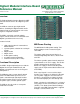
he following diagram shows how the MIB can
b
e configured to provide 3.3V from the VA bus
a
t header J1 and external power (VE, labeled
VCC” on J9) on the VB bus for header J2.
J1
J2
J3
J4
J5
J6
J7
J8
JP1
JP2
JP3
JP4
JP5
JP6
JP7
JP8
JP9
JP10
VA VB
VA VB
3.3V VE
VUVU
MIB Configuration
C
onnecting Devices to the MIB
D
igilent’s module boards are connected to the
M
IB using a Digilent 6-pin expansion cable.
T
hese cables are available in six and eighteen
n
ch versions.
F
or more information, see www.digilentinc.com.
Header (J10)
Module
Connectors Socket (J11)
To System
Board
6-Pin Headers
To Peripheral
Board
38 J1 1 4
36 2 6
35 3 5
34 4 8
33 J2 1 7
32 2 10
31 3 9
30 4 12
29 J3 1 11
28 2 14
27 3 13
26 4 16
25 J4 1 15
24 2 18
23 3 17
22 4 20
21 J5 1 19
20 2 22
19 3 21
18 4 24
17 J6 1 23
16 2 26
15 3 25
14 4 28
13 J7 1 27
12 2 30
11 3 29
10 4 32
9 J8 1 31
8 2 34
7 3 33
5 4 35
* For all 6-pin headers, the number 5 pins on are
connected to ground and the number 6 pins are
connected to power.
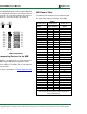
MIB Pinout Table
The table below shows the pin assignments for
the expansion and 6-pin headers on the MIB.