
Manual

D
D
i
i
g
g
i
i
l
l
e
e
n
n
t
t
M
M
o
o
d
d
u
u
l
l
a
a
r
r
I
I
n
n
t
t
e
e
r
r
f
f
a
a
c
c
e
e
B
B
o
o
a
a
r
r
d
d
R
R
e
e
f
f
e
e
r
r
e
e
n
n
c
c
e
e
M
M
a
a
n
n
u
u
a
a
l
l
®
www.digilentinc.com
R
evision: 3/11/05 215 E Main Suite D | Pullman, WA 99163
(509) 334 6306 Voice and Fax
D
oc: 502-057 page 1 of 2
Copyright Digilent, Inc. All rights reserved. Other product and company names mentioned may be trademarks of their respective owners.
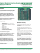
O
verview
T
he Digilent Modular Interface Board (the MIB)
c
onnects outside devices to a Digilent system
b
oard.
T
he MIB can connect up to eight outside
d
evices (including the Digilent module and h-
b
ridge boards) to system boards such as the
P
egasus or Spa
r
tan 3 boards.
T
he MIB is especially useful for robotics
p
rojects, where numerous I/O connections to a
D
igilent system board are necessary.
F
eatures include:
• eight 6-pin headers for connection to
module boards
• separate power selection for each 6-pin
header
• 40-pin header
• 40-pin socket
• flexible power routing
• test-point header functionality
• small form factor (2.20” x 2.20”).
F
unctional Description
T
he MIB is designed primarily for use with the
D
igilent line of 6-pin module boards, and
D
igilent system boards such as the Pegasus
a
nd Spartan 3.
T
he MIB plugs into a system board’s 40-pin
s
ocket. The MIB allows up to 32 user I/O
s
ignals, routed through eight 6-pin headers.
E
ach 6-pin header conveys four I/O signals,
o
ne power signal, and one ground signal.
T
he MIB can also be used as a test point
h
eader when needed.
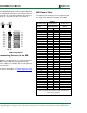
MIB Power Routing
The MIB allows flexible power routing. Two
distinct voltages can be created using the
same MIB.
The power supply from external devices is
routed through two power buses, labeled “VA”
and “VB”.
The VA bus provides power from the attached
system board’s 3.3V or VU supply. The VB bus
provides power from the attached system
board’s VU supply or from an outside power
supply (via the 2-pin terminal block labeled “J9”
on the MIB).
Each set of signals is accessed via a 6-pin
header. These headers are labeled J1 through
J8. The power supply bus for each of these
headers is selected using a jumper shunt on
the associated jumper pins JP1 through JP8.
Power selection for each power bus is selected
using jumper shunts at JP9 (VA bus) and JP10
(VB bus). This allows for two distinct voltages
using the same MIB. External power is applied
through a screw terminal at J9.