
Data Sheet

3/8/2018 Digital Discovery Reference Manual [Reference.Digilentinc]
https://reference.digilentinc.com/reference/instrumentation/digital-discovery/reference-manual 23/25
(https://reference.digilentinc.com/_detail/reference/instrumentation/digital-discovery/dd-high-speed-adapter-diagram-600.png?
id=reference%3Ainstrumentation%3Adigital-discovery%3Areference-manual)
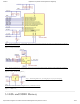
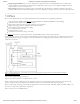
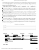
High Speed Logic Probes (datasheet (https://reference.digilentinc.com/_media/reference/instrumentation/digital-discovery/250-
104_dp_2.54_3.pdf)). Each twisted cable has a GND () (black) wire twisted to a DIN_USR (colored) wire. The wire connects to the
High Speed Adapter via a 2 pin female header, and two 1 pin female connectors to the device under test. A 100Ω resistor is
embedded in the signal wire, on the end closest to the device under test. All GND () wires should be connected to Ground of the
device under test.
This chapter shows the features and performances as described in the Digital Discovery Datasheet. Footnotes add detailed information and
annotate the HW description in this Manual.
24 high-speed input channels (DIN0…23), accessible through one 2×16 connector, used with the Logic Analyzer in WaveForms
(560kΩ||10pF)
16 digital I/Os (DIO24…39) arranged in two Pmod-style (2×6) connectors, used with the Logic Analyzer in WaveForms
800MSps input sample rate when using maximum 8 inputs (and the High Speed Adapter), 400 MSps with maximum 16 inputs (with
the High Speed Adapter), 200MSps and lower with maximum 32 inputs
User programmable input and output LVCMOS voltage levels from 1.2V to 3.3V (5V compatible )
100MHz signal input bandwidth
2Gbit DDR3 acquisition buffer for Logic Analyzer
Multiple trigger options including pin change, bus pattern, etc
Digital Bus Analyzers (SPI, I²C, UART, Parallel)
16 digital I/Os arranged in two Pmod-style (2×6) connectors.
Each of the 16 pins can be configured for input (Logic analyzer) or set as output .
Algorithmic pattern generator (no buffers used)
Custom pattern buffer/ch.: 32Ksamples
ROM () Logic for implementing user defined Boolean functions and State Machines
Bus Protocol Controllers (SPI, UART, I²C)
100MSps max. output sample rate (50MHz maximum output frequency).
Automatic or manual strength and slew settings for outputs.
User programmable logic I/O levels from 1.2V to 3.3V (5V compatible) , .
USB bus powered
User power supplies, 1.2V to 3.3V, available in the two Pmod-style connectors (100mA max)
Twisted wire high-speed cable option for input channels to insure signal integrity
Free WaveForms software runs on Windows, MacOS, and Linux
Cross-triggering between Logic Analyzer, Pattern Generator or external trigger
Data file import/export using standard formats
80X80X25mm, 80g (without accessories)
includes: USB cable, fly-wire accessory
Written by Mircea Dabacan, PhD, Technical University of Cluj-Napoca Romania
9. Features and Performances
9.1. Logic Analyzer
1)
2)
3) 4)
5)
9.2. Multi-purpose Digital I/O
6)
7)
8)
9) 10)
9.3. Other features