
Data Sheet

3/8/2018 Digital Discovery Reference Manual [Reference.Digilentinc]
https://reference.digilentinc.com/reference/instrumentation/digital-discovery/reference-manual 17/25
(https://reference.digilentinc.com/_detail/digital_discovery/dd_13vccioprogsupply.png?id=reference%3Ainstrumentation%3Adigital-
discovery%3Areference-manual)
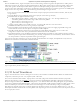
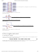
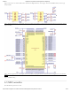
Figure 13. VCCIO_PROG supply. []
(https://reference.digilentinc.com/_detail/digital_discovery/dd_14vcciousrprotectionandswitch.png?id=reference%3Ainstrumentation%3Adigital-
discovery%3Areference-manual)
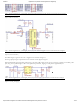
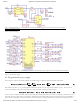
Figure 14. VCCIO_USR protection and switch. []
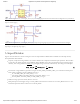
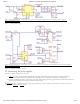
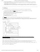
The microcontroller in Figure 15 has two roles:
1. A/D () Conversion of VVSNS_VBUS, VISNS_VBUS, VVSNS_USR, VISNS_USR, representing the voltages and currents
consumed from VBUS and VCCIO_USR respectively. The digital results are passed to the FPGA via an SPI interface.
2. Storing the calibration parameters computed as a part of the manufacturing test. During regular behavior, the WaveForms Software
reads the parameters and corrects both generated and acquired signals.
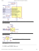
The DAC () in Figure 16 generates the setting voltage for programming the value of VCCIO. IC22 in Figure 17 provides 3V reference
voltage for both ADC () and DAC () above.
4.3. Monitoring the power supplies