
Data Sheet

Cmod A7 Reference Manual
Copyright Digilent, Inc. All rights reserved.
Other product and company names mentioned may be trademarks of their respective owners.
Page 8 of 10
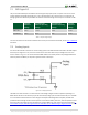
cycle of each color between 5-% and 0% causes the different colors to be illuminated at different intensities,
allowing virtually any color to be displayed.
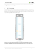
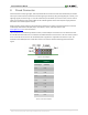
7 DIP Connector
The Cmod A7 has a 48-pin DIP connector for connecting to breadboards and custom fixtures. The pins have 100-
mil spacing, and the entire module is 0.7 inches by 2.75 inches. Of the 48-pins, 44 are connected directly to FPGA
Digital I/Os, two are voltage-divided and connected to FPGA analog inputs, and two are connected to power pins.
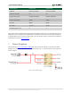
The pin numbering of the DIP connector is shown in Fig. 7.1.
Figure 7.1. DIP pin diagram.
VU (pin 24) can be used to power the Cmod A7 when it is not connected to a USB host. When the device is
connected to a USB host, VU is driven by the 5V rail of the USB connector and can be used to power devices
external to the Cmod A7. See the “Power” section of this manual for more information on powering the Cmod A7.