
Data Sheet

Cmod A7 Reference Manual
Copyright Digilent, Inc. All rights reserved.
Other product and company names mentioned may be trademarks of their respective owners.
Page 10 of 10
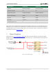
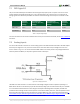
8 Pmod Connector
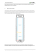
Pmod connecters are 2x6, right-angle, 100-mil spaced female connectors that mate with standard 2x6 pin headers.
Each 12-pin Pmod connector provides two 3.3V VCC signals (pins 6 and 12), two ground signals (pins 5 and 11), and
eight logic signals, as shown in Fig. 8.1. The VCC and Ground pins can deliver up to 1A of current, but care must be
taken not to exceed any of the power budgets of the onboard regulators of the external power supply (these are
described in the “Power Supplies” section).
Digilent produces a large collection of Pmod accessory boards that can attach to the Pmod expansion connectors
to add ready-made functions like A/Ds, D/As, motor drivers, sensors, and other functions. See
www.digilentinc.com for more information.
The Cmod A7 has one standard-type Pmod connector, and the FPGA pin connections for it are described in Table
8.1. Standard Pmod connectors are connected to the FPGA via 200-ohm series resistors. The series resistor prevent
short circuits that can occur if the user accidentally drives a signal that is supposed to be used as an input. The
downside to this added protection is that these resistors can limit the maximum switching speed of the data
signals.
Figure 8.1. Pmod diagram.
Pmod JA
Pmod Type
Standard
Pin 1
G17
Pin 2
G19
Pin 3
N18
Pin 4
L18
Pin 7
H17
Pin 8
H19
Pin 9
J19
Pin 10
K18
Table 8.1. Cmod A7 Pmod pinout.