
User guide


Digilent Cerebot Plus Reference Manual Digilent, Inc.
www.digilentinc.com page 8 of 13
Copyright Digilent, Inc. All rights reserved. Other product and company names mentioned may be trademarks of their respective owners.
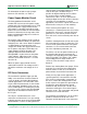
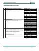
Pmod Headers and SPI Connection
Pin Description *All Pmod headers can be used as general
purpose IOs or for the following specific purposes.
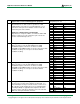
Cerebot Plus Pmod header pins to
Atmega64L ports / bit
JA External memory bus
These pins connect to the multiplexed Address/Data line of
the ATmega2560 external memory bus interface.
Pin Function Port/ bit
1 AD0 PA0
2 AD1 PA1
3 AD2 PA2
4 AD3 PA3
5 GND
6 VCC
7 AD4 PA4
8 AD5 PA5
9 AD6 PA6
10 AD7 PA7
11 GND
12 VCC
JB External memory bus
These pins connect to the higher order address pins of the
ATmega2560 external memory bus interface.
1 A8 PC0
2 A9 PC1
3 A10 PC2
4 A11 PC3
5 GND
6 VCC
7 A12 PC4
8 A13 PC5
9 A14 PC6
10 A15 PC7
11 GND
12 VCC
JC Serial port communications
Connection to UART0. A PmodRS232™ can be used on this
connector for an RS232 serial interface. JC shares the RXD0
and TXD0 pins with the ISP ports. No device can be
connected to JC during in-system programming.
External memory bus
Pins 7-9 connect to the control signals of the ATmega2560
external memory bus interface.
1 XCK0/ AIN0 PE2
2 OC3A/ AIN1 PE3
3 RXD0/ PDI PE0
4 TXD0/ PDO PE1
5 GND
6 VCC
7 WR PG0
8 RD PG1
9 ALE PG2
10 TOSC2 PG3
11 GND
12 VCC