
User guide


Digilent Cerebot Plus Reference Manual Digilent, Inc.
www.digilentinc.com page 11 of 13
Copyright Digilent, Inc. All rights reserved. Other product and company names mentioned may be trademarks of their respective owners.
Pin Description *All Pmod headers can be used as general
purpose IOs or for the following specific purposes.
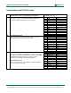
Cerebot Plus Pmod header pins to
Atmega64L ports / bit
JH H-bridge connection with input capture
This port can be used to provide multiple pulse width
modulated outputs to run motors. It can be used with
PmodHB3 or PmodHB5 modules to run up to two motors with
feedback encoding, or to run up to four motors without
feedback encoding.
Serial port communications
Pins 3 & 4 provide connection to UART2. A PmodRS232™
can be used on this connector for an RS232 serial interface.
1 XCK2 PH2
2 OC4A PH3
3 RXD2 PH0
4 TXD2 PH1
5 GND
6 VCC
7 T4 PH7
8 OC4B PH4
9 OC2B PH6
10 OC4C PH5
11 GND
12 VCC
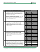
JJ Analog input
Inputs to the analog to digital converter of the Atmega2560.
ADC0 and ADC1 are connected to the Cerebot Plus board’s
voltage monitoring circuits. ADC0 is the input for monitoring
VU board power and ADC1 is connected to VS for monitoring
the independent servo power.
Analog or JTAG input
The default fuse setting for the Cerebot Plus is to disable the
JTAG input and provide analog inputs. The Atmega2560 fuse
settings have to be changed to enable the JTAG interface to
use JJ as a JTAG device input (e.g., to use the Atmel
JTAGICE mkII).
Servo connectors
The pins on JJ are shared with the servo connectors S1-S8.
1 ADC0 PF 0
2 ADC1 PF 1
3 ADC2 PF 2
4 ADC3 PF 3
5 GND
6 VCC
7 ADC5/ TMS PF 5
8 ADC7/ TDI PF 7
9 ADC6/ TDO PF 6
10 ADC4/ TCK PF 4
11 GND
12 VCC
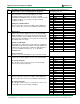
JK Analog input
Inputs to the analog to digital converter of the Atmega2560.
Pin change interrupt
All of the pins on this connector can be used as interrupt
sources for pin change interrupts.
1 ADC8 PK 0
2 ADC9 PK 1
3 ADC10 PK 2
4 ADC11 PK 3
5 GND
6 VCC
7 ADC12 PK 4
8 ADC13 PK 5
9 ADC14 PK 6
10 ADC15 PK 7
11 GND
12 VCC
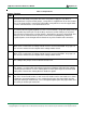
JL Serial port communications
Pins 3 & 4 provide connection to UART3. A PmodRS232™
can be used on this connector for an RS232 serial interface.
Pin change interrupt
All of the pins on this connector, except pin 10, can be used
as interrupt sources for pin change interrupts.
1 XCK3 PJ 2
2 PCINT12 PJ 3
3 RXD3 PJ 0
4 TXD3 PJ 1
5 GND
6 VCC
7 PCINT13 PJ 4
8 PCINT14 PJ 5
9 PCINT15 PJ 6
10 PJ7 PJ 7
11 GND
12 VCC