
Data Sheet

3/8/2018 Arty Z7 Reference Manual [Reference.Digilentinc]
https://reference.digilentinc.com/reference/programmable-logic/arty-z7/reference-manual 21/24
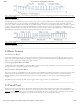
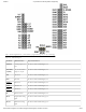
Pin Name Shield Function Arty Z7 Connection
V_P, V_N Dedicated
Differential Analog
Input
See Section titled “Shield Analog I/O”
XGND XADC Analog
Ground
Connected to net used to drive the XADC ground reference on the Zynq (VREFN)
XVREF XADC Analog
Voltage Reference
Connected to 1.25 V, 25mA rail used to drive the XADC voltage reference on the Zynq
(VREFP)
Not Connected Not Connected
IOREF Digital I/O Voltage
reference
Connected to the Arty Z7 3.3V Power Rail (See the “Power Supplies” section)
RST Reset to Shield Connected to the red “SRST” button and MIO pin 12 of the Zynq. When JP1 is shorted, it is
also connected to the DTR signal of the FTDI USB-UART bridge.
3V3 3.3V Power Rail Connected to the Arty Z7 3.3V Power Rail (See the “Power Supplies” section)
5V0 5.0V Power Rail Connected to the Arty Z7 5.0V Power Rail (See the “Power Supplies” section)
GND (), G Ground Connected to the Ground plane of Arty Z7
VIN Power Input Connected in parallel with the external power supply connector (J18).
Table 16.1. Shield Pin Descriptions.
The pins connected directly to the Zynq PL can be used as general purpose inputs or outputs. These pins include the I2C, SPI, and general
purpose I/O pins. There are 200 Ohm series resistors between the FPGA and the digital I/O pins to help provide protection against
accidental short circuits (with the exception of the AN5-AN0 signals, which have no series resistors, and the AN6-AN12 signals, which have
100 Ohm series resistors). The absolute maximum and recommended operating voltages for these pins are outlined in the table below.
IO26-IO41 and A (IO42) are not accessible on the Arty Z7-10. Also, AN0-AN5 cannot be used as Digital I/O on the Arty Z7-10. This is
due to fewer number of I/O pins being available on the Zynq-7010 than on the Zynq-7020.
Absolute
Minimum Voltage
Recommended Minimum
Operating Voltage
Recommended Maximum
Operating Voltage
Absolute
Maximum Voltage
Powered -0.4 V -0.2 V 3.4 V 3.75 V
Unpowered -0.4 V N/A N/A 0.55 V
Table 16.1.1. Shield Digital Voltages.
For more information on the electrical characteristics of the pins connected to the Zynq PL, please see the Zynq-7000 datasheet
(http://www.xilinx.com/support/documentation/data_sheets/ds187-XC7Z010-XC7Z020-Data-Sheet.pdf) from Xilinx.
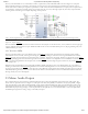
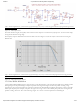
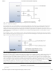
The pins labeled A0-A11 and V_P/V_N are used as analog inputs to the XADC module of the Zynq. The Zynq expects that the inputs
range from 0-1 V. On the pins labeled A0-A5 we use an external circuit to scale down the input voltage from 3.3V. This circuit is shown in
Figure 16.2.1. This circuit allows the XADC module to accurately measure any voltage between 0V and 3.3V (relative to the Arty Z7's GND
()) that is applied to any of these pins. If you wish to use the pins labeled A0-A5 as Digital inputs or outputs, they are also connected directly
to the Zynq PL before the resistor divider circuit (also shown in Figure 16.2.1) on the Arty Z7-20. This additional connection is not made
on the Arty Z7-10, which is why these signals can only be used as analog inputs on that variant.
16.1 Shield Digital I/O
16.2 Shield Analog I/O