
Data Sheet

3/8/2018 Arty Z7 Reference Manual [Reference.Digilentinc]
https://reference.digilentinc.com/reference/programmable-logic/arty-z7/reference-manual 19/24
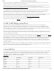
(https://reference.digilentinc.com/_detail/reference/programmable-logic/arty-z7/arty-z7-pmod.png?id=reference%3Aprogrammable-logic%3Aarty-
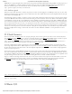
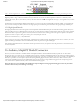
z7%3Areference-manual) Figure 15.1. Pmod Port Diagram
Digilent produces a large collection of Pmod accessory boards that can attach to the Pmod expansion connectors to add ready-made
functions like A/D’s, D/A’s, motor drivers, sensors, and other functions. See www.digilentinc.com (http://www.digilentinc.com) for more
information.
Each Pmod port found on Digilent FPGA boards falls into one of four categories: standard, MIO connected, XADC, or high-speed. The
Arty Z7 has two Pmod ports, both of which are the high-speed type. The following section describes the high-speed type of Pmod port.
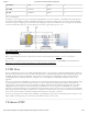
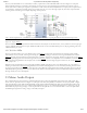
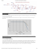
The High-speed Pmods have their data signals routed as impedance matched differential pairs for maximum switching speeds. They have
pads for loading resistors for added protection, but the Arty Z7 ships with these loaded as 0-Ohm shunts. With the series resistors shunted,
these Pmods offer no protection against short circuits, but allow for much faster switching speeds. The signals are paired to the adjacent
signals in the same row: pins 1 and 2, pins 3 and 4, pins 7 and 8, and pins 9 and 10.
Traces are routed 100 ohm (+/- 10%) differential.
If pins on this port are used as single-ended signals, coupled pairs may exhibit crosstalk. In applications where this is a concern, one of the
signals should be grounded (drive it low from the FPGA) and use its pair for the signal-ended signal.
Since the High-Speed Pmods have 0-ohm shunts instead of protection resistors, the operator must take precaution to ensure that they do
not cause any shorts.
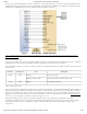
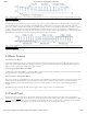
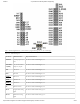
The Arty Z7 can be connected to standard Arduino and chipKIT shields to add extended functionality. Special care was taken while
designing the Arty Z7 to make sure it is compatible with the majority of Arduino and chipKIT shields on the market. The shield connector
has 49 pins connected to the Zynq PL for general purpose Digital I/O on the Arty Z7-20 and 26 on the Arty Z7-10. Due to the flexibility of
FPGAs, it is possible to use these pins for just about anything including digital read/write, SPI connections, UART connections, I2C
connections, and PWM. Six of these pins (labeled AN0-AN5) can also be used as single-ended analog inputs with an input range of 0V-
3.3V, and another six (labeled AN6-11) can be used as differential analog inputs.
Note: The Arty Z7 is not compatible with shields that output 5V digital or analog signals. Driving pins on the Arty Z7 shield
connector above 5V may cause damage to the Zynq.
15.1 High-Speed Pmods
16 Arduino/chipKIT Shield Connector