
Data Sheet

3/8/2018 Arty Z7 Reference Manual [Reference.Digilentinc]
https://reference.digilentinc.com/reference/programmable-logic/arty-z7/reference-manual 17/24
(https://reference.digilentinc.com/_detail/reference/programmable-logic/arty-z7/arty-z7-audio-sch.png?id=reference%3Aprogrammable-logic%3Aarty-
z7%3Areference-manual)
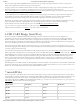
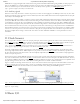
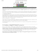
Figure 13.1. Audio Output Circuit.
The Audio shut-down signal (AUD_SD) is used to mute the audio output. It is connected to Zynq PL pin T17. To use the audio output,
this signal must be driven to logic high.
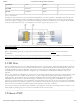
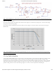
The frequency response of SK Butterworth Low-Pass Filter is shown in Figure 13.2. The AC analysis of the circuit is done using NI
Multisim 12.0.
(https://reference.digilentinc.com/_detail/reference/programmable-logic/arty-z7/arty-z7-audio-chart-nolabel.png?id=reference%3Aprogrammable-
logic%3Aarty-z7%3Areference-manual)
Figure 13.2. Audio Output Frequency Response.
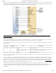
A pulse-width modulated (PWM) signal is a chain of pulses at some fixed frequency, with each pulse potentially having a different width.
This digital signal can be passed through a simple low-pass filter that integrates the digital waveform to produce an analog voltage
proportional to the average pulse-width over some interval (the interval is determined by the 3dB cut-off frequency of the low-pass filter
and the pulse frequency). For example, if the pulses are high for an average of 10% of the available pulse period, then an integrator will
produce an analog value that is 10% of the Vdd voltage. Figure 13.1.1 shows a waveform represented as a PWM signal.
13.1 Pulse-Width Modulation