
Data Sheet

3/8/2018 Arty Z7 Reference Manual [Reference.Digilentinc]
https://reference.digilentinc.com/reference/programmable-logic/arty-z7/reference-manual 15/24
HDMI/DVI is a high-speed digital video stream interface using transition-minimized differential signaling (TMDS). To make proper use of
either of the HDMI ports, a standard-compliant transmitter or receiver needs to be implemented in the Zynq PL. The implementation
details are outside the scope of this manual. Check out the vivado-library IP Core repository on the Digilent github
(https://github.com/Digilent) for ready-to-use reference IP.
Whenever a sink is ready and wishes to announce its presence, it connects the 5V0 supply pin to the HPD pin. On the Arty Z7, this is done
by driving the Hot Plug Assert signal high. Note this should only be done after a DDC channel slave has been implemented in the Zynq PL
and is ready to transmit display data.
The Display Data Channel, or DDC, is a collection of protocols that enable communication between the display (sink) and graphics adapter
(source). The DDC2B variant is based on I2C, the bus master being the source and the bus slave the sink. When a source detects high level
on the HPD pin, it queries the sink over the DDC bus for video capabilities. It determines whether the sink is DVI or HDMI-capable and
what resolutions are supported. Only afterwards will video transmission begin. Refer to VESA E-DDC specifications for more information.
The Consumer Electronics Control, or CEC, is an optional protocol that allows control messages to be passed around on an HDMI chain
between different products. A common use case is a TV passing control messages originating from a universal remote to a DVR or satellite
receiver. It is a one-wire protocol at 3.3V level connected to a Zynq PL user I/O pin. The wire can be controlled in an open-drain fashion
allowing for multiple devices sharing a common CEC wire. Refer to the CEC addendum of HDMI 1.3 or later specifications for more
information.
The Arty Z7 provides a 50 MHz () clock to the Zynq PS_CLK input, which is used to generate the clocks for each of the PS subsystems.
The 50 MHz () input allows the processor to operate at a maximum frequency of 650 MHz () and the DDR3 memory controller to operate
at a maximum of 525 MHz () (1050 Mbps). The Arty Z7 Zynq Presets file available on the Arty Z7 Resource Center
(https://reference.digilentinc.com/reference/programmable-logic/arty-z7/start) can be imported into the Zynq Processing System IP core in a
Vivado project to properly configure the Zynq to work with the 50 MHz () input clock.
The PS has a dedicated PLL capable of generating up to four reference clocks, each with settable frequencies, that can be used to clock
custom logic implemented in the PL. Additionally, the Arty Z7 provides an external 125 MHz () reference clock directly to pin H16 of the
PL. The external reference clock allows the PL to be used completely independently of the PS, which can be useful for simple applications
that do not require the processor.
The PL of the Zynq also includes MMCM’s and PLL’s that can be used to generate clocks with precise frequencies and phase relationships.
Any of the four PS reference clocks or the 125 MHz () external reference clock can be used as an input to the MMCMs and PLLs. The Arty
Z7-10 includes 2 MMCM's and 2 PLL's, and the Arty Z7-20 includes 4 MMCM's and 4 PLL's. For a full description of the capabilities of the
Zynq PL clocking resources, refer to the “7 Series FPGAs Clocking Resources User Guide” available from Xilinx.
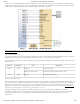
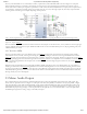
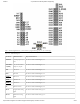
Figure 11.1 outlines the clocking scheme used on the Arty Z7. Note that the reference clock output from the Ethernet PHY is used as the
125 MHz () reference clock to the PL, in order to cut the cost of including a dedicated oscillator for this purpose. Keep in mind that
CLK125 will be disabled when the Ethernet PHY (IC1) is held in hardware reset by driving the PHYRSTB signal low.
(https://reference.digilentinc.com/_detail/reference/programmable-logic/arty-z7/arty-z7-clocking.png?id=reference%3Aprogrammable-logic%3Aarty-
z7%3Areference-manual)
Figure 11.1. Arty Z7 clocking.
10.2 Auxiliary signals
11 Clock Sources
12 Basic I/O