
Data Sheet

3/8/2018 Arty Z7 Reference Manual [Reference.Digilentinc]
https://reference.digilentinc.com/reference/programmable-logic/arty-z7/reference-manual 13/24
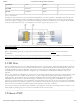
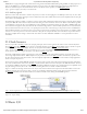
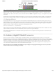
The Arty Z7 uses a Realtek RTL8211E-VL PHY to implement a 10/100/1000 Ethernet port for network connection. The PHY connects
to MIO Bank 501 (1.8V) and interfaces to the Zynq-7000 APSoC via RGMII for data and MDIO for management. The auxiliary interrupt
(INTB) and reset (PHYRSTB) signals connect to MIO pins MIO10 and MIO9, respectively.
(https://reference.digilentinc.com/_detail/reference/programmable-logic/arty-z7/arty-z7-eth.png?id=reference%3Aprogrammable-logic%3Aarty-
z7%3Areference-manual)
Figure 9.1. Ethernet PHY signals
After power-up the PHY starts with Auto Negotiation enabled, advertising 10/100/1000 link speeds and full duplex. If there is an Ethernet-
capable partner connected, the PHY automatically establishes a link with it, even with the Zynq not configured.
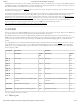
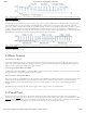
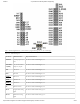
Two status indicator LEDs are on-board near the RJ-45 connector that indicate traffic (LD9) and valid link state (LD8). Table 9.1 shows the
default behavior.
Function Designator State Description
LINK LD8 Steady On Link 10/100/1000
Blinking 0.4s ON, 2s OFF Link, Energy Efficient Ethernet (EEE) mode
ACT LD9 Blinking Transmitting or Receiving
Table 9.1. Ethernet status LEDs.
The Zynq incorporates two independent Gigabit Ethernet Controllers. They implement a 10/100/1000 half/full duplex Ethernet MAC. Of
these two, GEM 0 can be mapped to the MIO pins where the PHY is connected. Since the MIO bank is powered from 1.8V, the RGMII
interface uses 1.8V HSTL Class 1 drivers. For this I/O standard an external reference of 0.9V is provided in bank 501 (PS_MIO_VREF).
Mapping out the correct pins and configuring the interface is handled by the Arty Z7 Zynq Presets file, available on the Arty Z7 Resource
Center (https://reference.digilentinc.com/reference/programmable-logic/arty-z7/start).
Although the default power-up configuration of the PHY might be enough in most applications, the MDIO bus is available for
management. The RTL8211E-VL is assigned the 5-bit address 00001 on the MDIO bus. With simple register read and write commands,
status information can be read out or configuration changed. The Realtek PHY follows industry-standard register map for basic
configuration.