
Data Sheet
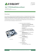

Arty FPGA Board Reference Manual
Copyright Digilent, Inc. All rights reserved.
Other product and company names mentioned may be trademarks of their respective owners.
Page 7 of 18
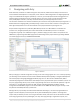
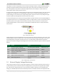
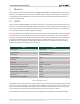
Figure 3.3.1. 5V supply power consumption.
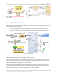
4 FPGA Configuration
After power-on, the Artix-7 FPGA must be configured (or programmed) before it can perform any function. You can
configure the FPGA in one of two ways:
1. A PC can use the Digilent USB-JTAG circuitry (port J10) to program the FPGA any time the power is on.
2. A file stored in the nonvolatile serial (SPI) flash device can be transferred to the FPGA using the SPI port.
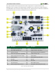
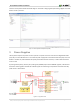
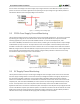
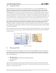
Figure 4.1. Arty configuration.
Figure 3 shows the different options available for configuring the FPGA. An on-board “mode” jumper (JP1) selects
whether the FPGA will be programmed by the Quad-SPI flash on power up.
The FPGA configuration data is stored in files called bitstreams that have the .bit file extension. The ISE or Vivado
software from Xilinx can create bitstreams from VHDL, Verilog, or schematic-based source files (in the ISE toolset,
EDK is used for MicroBlaze embedded processor-based designs).
Bitstreams are stored in volatile memory cells within the FPGA. This data defines the FPGA’s logic functions and
circuit connections, and it remains valid until it is erased by removing board power, by pressing the reset button
attached to the PROG input, or by writing a new configuration file using the JTAG port.