
Data Sheet

Arty FPGA Board Reference Manual
Copyright Digilent, Inc. All rights reserved.
Other product and company names mentioned may be trademarks of their respective owners.
Page 5 of 18
The USB port can deliver enough power for the vast majority of designs. However, a few demanding applications,
including any that drive multiple peripheral boards, might require more power than the USB port can provide.
Also, some applications may need to run without being connected to a PC’s USB port. In these instances, an
external power supply or battery pack can be used.
An external power supply can be used by plugging into Power Jack J12 and installing a jumper in the “REG” position
on Header J13. The supply must use a coaxial, center-positive 2.1mm (or 2.5mm) internal-diameter plug, and
provide a voltage of 7 to 15 Volts DC. The supply should provide a minimum current of 1 amp. Ideally, the supply
should be capable of providing 36 Watts of power (12 Volts DC, 3 amps).
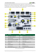
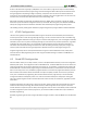
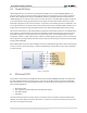
An external battery pack can be used by connecting the battery's positive terminal to pin 8 of J7 (labeled VIN) and
the negative terminal to pin 7 of J7 (labeled GND), as shown in the figure below. In order to use the battery pack as
the board’s power source a jumper must be installed in the “REG” position on Header J13. The battery must
provide a voltage between 7 and 15 volts DC, and should NOT be installed while there is a supply connected to
Power Jack J12.
Figure 3.2. Battery pack connection.
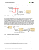
Voltage regulator circuits from Analog Devices and Texas Instruments create the required 3.3V, 1.8V, 1.35V, 1.25V,
and 0.95V supplies from the 5V power source. In the event that an external supply or battery pack is used, the on-
board Analog Devices 5V regulator provides the 5V source. The table below provides additional information
(typical currents depend strongly on FPGA configuration and the values provided are typical of medium size/speed
designs).
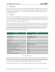
Table 2. Voltage regulator circuit information.
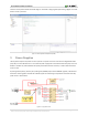
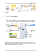
3.1 External Supply Voltage Monitoring
The Arty board includes circuitry for monitoring the voltage of an external supply connected to Power Jack J12, or
an external battery pack connected to header J7. A voltage divider is used to scale the unregulated input voltage,
VU, to be within the range (0-1V) that the on-chip 12-bit ADC is capable of measuring. The unregulated input
voltage, VU, is divided by 16 and then fed into Auxiliary Channel 2 on the XADC of the Artix 35T. Applications that
Supply
Circuits
Device
Current (max/typical)
5V
On-board regulators, RGB LEDs
IC12: Analog Devices ADP2384
3.5A/0.375A to 2A
3.3V
FPGA I/O, clocks, flash, Pmods, LEDs,
buttons, switches, USB port, Ethernet
IC11: Analog Devices ADP5052
2.2A/NA
0.95V
FPGA Core and Block RAM
IC11: Analog Devices ADP5052
1.0A/0.2A to 0.8A
1.8V
FPGA Auxiliary
IC11: Analog Devices ADP5052
1.0A/NA
1.35V
DDR3L and associated FPGA bank
IC11: Analog Devices ADP5052
1.0A/NA
1.25V
XADC analog reference
IC13: Texas Instruments
REF3012
25mA/NA