
Data Sheet

Arty FPGA Board Reference Manual
Copyright Digilent, Inc. All rights reserved.
Other product and company names mentioned may be trademarks of their respective owners.
Page 11 of 18
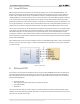
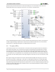
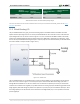
Vivado IPI-based designs can access the PHY using either the AXI EthernetLite IP core, the AXI 1G/2.5G Ethernet
Subsystem IP core, or the Tri Mode Ethernet MAC IP core. A 25 MHz clock needs to be generated for the X1 pin of
the external PHY, labeled ETH_REF_CLK in the Arty Schematic. To learn how to properly use the Ethernet PHY in a
MicroBlaze design on the Arty, refer to the Getting Started with MicroBlaze Servers tutorial from the Arty Resource
Center.
For further information on the Ethernet PHY, refer to the DP83848J datasheet.
Figure 6.1. Arty Ethernet.
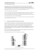
7 Oscillators/Clocks
The Arty board includes a single 100 MHz crystal oscillator connected to pin E3 (E3 is a MRCC input on bank 35).
The input clock can drive MMCMs or PLLs to generate clocks of various frequencies and with known phase
relationships that may be needed throughout a design. Some rules restrict which MMCMs and PLLs may be driven
by the 100 MHz input clock. For a full description of these rules and of the capabilities of the Artix-7 clocking
resources, refer to the “7 Series FPGAs Clocking Resources User Guide” available from Xilinx.
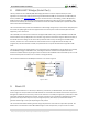
Xilinx offers the Clocking Wizard IP core to help users generate the different clocks required for a specific design.
This wizard will properly instantiate the needed MMCMs and PLLs based on the desired frequencies and phase
relationships specified by the user. The wizard will then output an easy-to-use wrapper component around these
clocking resources that can be inserted into the user’s design. The clocking wizard can be accessed from within the
Project Navigator or Core Generator tools.