
Data Sheet

Arty FPGA Board Reference Manual
Copyright Digilent, Inc. All rights reserved.
Other product and company names mentioned may be trademarks of their respective owners.
Page 10 of 18
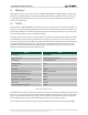
5.2 Quad-SPI Flash
FPGA configuration files can be written to the Quad-SPI Flash (Micron part number N25Q128A13ESF40), and
setting the mode jumper will cause the FPGA to automatically read a configuration from this device at power on.
An Artix-7 35T configuration file requires 17,536,096 bits of memory, leaving about 87% of the flash device (or
~14MB) available for user data. A common use for this extra memory is to store MicroBlaze programs too big to fit
in the onboard Block memory (typically 128 KB). These programs are then loaded and executed using a smaller
bootloader program that can fit in the block memory. It is possible to automatically generate this bootloader, roll it
into a single file (called an .mcs file) that also contains the bitstream and your custom MicroBlaze application, and
program this file into SPI Flash using Xilinx SDK and Vivado. Xilinx Answer Record 63605 explains how to do this.
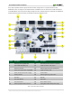
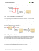
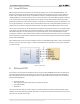
The contents of the memory can be manipulated by issuing certain commands on the SPI bus. The implementation
of this protocol is outside the scope of this document. All signals in the SPI bus are general-purpose user I/O pins
after FPGA configuration. On other boards, SCK is an exception because it remains a dedicated pin even after
configuration, however, on Arty the SCK signal is routed to an additional general purpose pin that can be accessed
after configuration (see Figure below). This allows access to this pin without having to instantiate the special FPGA
primitive called STARTUPE2.
Xilinx's AXI Quad SPI core can be used to read/write the flash in a MicroBlaze design. Refer to Xilinx's product guide
for this core to learn more about using it, or to Micron's datasheet for the flash device to learn how to implement
a custom controller.
Figure 5.1. Arty SPI flash.
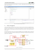
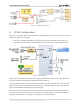
6 Ethernet PHY
Arty includes a Texas Instruments 10/100 Ethernet PHY (TI part number DP83848J) paired with an RJ-45 Ethernet
jack with integrated magnetics and indicator LEDs. The TI PHY uses the MII interface and supports 10/100 Mb/s.
Figure 5 illustrates the pin connections between the Artix-7 and the Ethernet PHY. At power-on reset, the PHY is
set to the following defaults:
MII mode interface
Auto-negotiation enabled, advertising all 10/100 mode capable
PHY address=00001
LED Mode 2
Two LEDs found in the Ethernet connector (J9) are connected to the PHY to provide link status and data activity
feedback. See the PHY datasheet for details. Note that it is normal for one LED to be illuminated and one to be off,
even when not using the Ethernet PHY.