USB-1208HS-4AO High-Speed Analog Input and Digital I/O User's Guide Document Revision 4 July 2014 © Copyright 2014
Your new Measurement Computing product comes with a fantastic extra — Management committed to your satisfaction! Thank you for choosing a Measurement Computing product—and congratulations! You own the finest, and you can now enjoy the protection of the most comprehensive warranties and unmatched phone tech support. It’s the embodiment of our mission: To provide data acquisition hardware and software that will save time and save money.
Table of Contents Preface About this Manual ................................................................................................................................. 5 Conventions ........................................................................................................................................................ 5 Where to find more information .........................................................................................................................
USB-1208HS-4AO User's Guide Environmental .................................................................................................................................................. 21 Mechanical ....................................................................................................................................................... 22 Screw terminal connector and pinout ...............................................................................................................
Preface About this Manual This document describes the USB-1208HS-4AO data acquisition device and lists device specifications. Conventions For more information Text presented in a box signifies additional information related to the subject matter. Caution! Shaded caution statements present information to help you avoid injuring yourself and others, damaging your hardware, or losing your data. bold text Bold text is used for the names of objects on a screen, such as buttons, text boxes, and check boxes.
Chapter 1 Introducing the USB-1208HS-4AO The USB-1208HS-4AO is a high-speed analog input and digital I/O data acquisition device providing the following features: Eight 13-bit single-ended (SE) or four differential (DIFF) analog inputs Four 12-bit analog outputs One external clock input and one external output for analog inputs One external clock input and one external output for analog outputs One digital trigger input 16 individually configurable digital I/O channels Two 32-bit counter
Chapter 2 Installing the USB-1208HS-4AO What comes with your shipment? The following items are shipped with the USB-1208HS-4AO: Hardware USB-1208HS-4AO USB cable Software MCC DAQ CD Documentation In addition to this hardware user's guide, you should also receive the Quick Start Guide. This booklet provides an overview of the MCC DAQ software you received with the device, and includes information about installing the software.
USB-1208HS-4AO User's Guide Installing the USB-1208HS-4AO Caution! Do not disconnect any device from the USB bus while the computer is communicating with the device, or you may lose data and/or your ability to communicate with the USB-1208HS-4AO.. If the Status LED turns off The Status LED turns off if communication is lost between the device and the computer. To restore communication, disconnect the USB cable from the computer and reconnect it. The Status LED should turn on.
Chapter 3 Functional Details Analog input acquisition modes The USB-1208HS-4AO can acquire analog input data in two basic modes – software paced and hardware paced. Software paced mode You can acquire one analog sample at a time in software paced mode. You initiate the A/D conversion by calling a software command. The analog value is converted to digital data and returned to the computer. You can repeat this procedure until you have the total number of samples that you want.
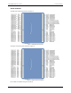
USB-1208HS-4AO User's Guide Functional Details Screw terminals The differential mode pinout is shown in Figure 3. Figure 3. Differential mode pinout The single-ended mode pinout is shown in Figure 4. Figure 4. Single-ended mode pinout Use 16 AWG to 30 AWG for signal connections.
USB-1208HS-4AO User's Guide Functional Details USB connector The USB connector provides +5 V power and communication. No external power supply is required. Activity LED The Activity LED indicates the communication status of the USB-1208HS-4AO. It blinks when data is transferred, and is off when the device is not communicating. This LED uses up to 10 mA of current and cannot be disabled. Status LED The Status LED turns on when the device is detected and installed on the computer.
USB-1208HS-4AO User's Guide Functional Details Figure 5 depicts a voltage source connected to a USB-1208HS-4AO configured for SE mode. Figure 5. Single-ended measurement connection Figure 6 depicts a Wheatstone bridge signal source connected to a USB-1208HS-4AO configured for DIFF mode. Figure 6.
USB-1208HS-4AO User's Guide Functional Details You can connect an external clock signal to AICKI and/or AOCKI. When using an external clock, AICKO outputs the pulse generated from AOCKI , and AOCKO outputs the pulse generated from AOCKI When using the internal clock, AICKO outputs the ADC scan clock, and AOCKO outputs the DAC scan clock. Digital I/O You can connect up to 16 digital I/O lines to screw terminals DIO0 through DIO15.
USB-1208HS-4AO User's Guide Functional Details Figure 9. Location of W34 jumper (default pull-down setting shown) Figure 10. Pull-down and pull-up configurations 1. Replace the top section of the case, and then fasten it to the bottom section with the four screws. For more information on digital signal connections For general information regarding digital signal connections and digital I/O techniques, refer to the Guide to DAQ Signal Connections (available on our web site at www.mccdaq.
USB-1208HS-4AO User's Guide Functional Details Both the period and time delay ranges are 50 ns to 107.4 seconds. Figure 11. USB-1208HS-4AO PWM timer channel Trigger input The TRIG connection is an external digital trigger input. The trigger mode is software selectable for: Level-sensitive or edge-sensitive Rising or falling edge High or low level The default setting at power up is edge sensitive, rising edge.
Chapter 4 Specifications All specifications are subject to change without notice. Typical for 25 °C unless otherwise specified. Specifications in italic text are guaranteed by design. Analog input Table 1.
USB-1208HS-4AO User's Guide Specifications Table 2. Calibrated absolute accuracy Range Accuracy (mV) ±20 V (DIFF mode) ±10 V (DIFF mode) ±5 V (DIFF mode) ±10 V (SE mode) ±5 V (SE mode) ±2.5 V (SE mode) 0 – 10 V (SE mode) ±9.55 typ, ±13.18 max ±4.59 typ, ±6.23 max ±2.25 typ, ±2.75 max ±5.10 typ, ±8.06 max ±2.63 typ, ±4.03 max ±1.59 typ, ±2.70 max ±3.29 typ, ±5.13 max Table 3 summarizes the noise performance for the USB-1208HS-4AO.
USB-1208HS-4AO User's Guide Specifications Analog output Table 5. Analog output specifications Parameter D/A converter Number of channels Resolution Output range Output transient D/A update rate Sample clock source Monotonicity Output current Output short-circuit protection Output coupling Power up and reset state Output noise Settling time (to 0.
USB-1208HS-4AO User's Guide Specifications External trigger Table 7. External trigger specifications Parameter Specification Trigger source Trigger mode TRIG input Software-selectable for edge or level sensitive, rising or falling edge, high or low level. Power on default is edge sensitive, rising edge. 1 µs + 1 clock cycle max 100 ns min Schmitt trigger, 33 Ω series resistor and 47 kΩ pull-down to ground 0.4 V to 1.2 V 2.2 V min 5.5 V absolute max 1.5 V max –0.
USB-1208HS-4AO User's Guide Specifications Counters Table 9. Counter specifications Parameter Specification Counter terminal names Counter type Number of channels Input type Schmitt trigger hysteresis Input high voltage CTR0, CTR1 Event counter 2 Schmitt trigger, 33 Ω series resistor, 47 kΩ pull-down to ground 0.4 V to 1.2 V 2.2 V min 5.5 V absolute max 1.5 V max –0.
USB-1208HS-4AO User's Guide Specifications Power Table 12.
USB-1208HS-4AO User's Guide Specifications Mechanical Table 15. Mechanical specifications Parameter Specification Dimensions (L × W × H) 5.00 × 3.53 × 1.40 in. (127 × 89.9 × 35.6 mm) Screw terminal connector and pinout Table 16. Connector specifications Parameter Specification Connector type Wire gauge range Screw terminal 16 AWG to 30 AWG Table 17.
USB-1208HS-4AO User's Guide Specifications Table 18.
Declaration of Conformity Manufacturer: Address: Category: Measurement Computing Corporation 10 Commerce Way Suite 1008 Norton, MA 02766 USA Electrical equipment for measurement, control and laboratory use.
Measurement Computing Corporation 10 Commerce Way Suite 1008 Norton, Massachusetts 02766 (508) 946-5100 Fax: (508) 946-9500 E-mail: info@mccdaq.com www.mccdaq.