User Guide
Manuals
Brands
Digilent Manuals
Data Communication and Human Input Devices
MCC E-1608 Multifunction Ethernet DAQ Device
11
12
13
14
15
16
17
18
19
20
Table Of Contents
About this User's Guide
What you will learn from this user's guide
Conventions in this user's guide
Where to find more information
Introducing the E-1608
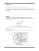
Ethernet interface
Functional block diagram
Installing the E-1608
Unpacking
Installing the software
Connecting the external power adapter
Connecting the E-1608
Configuring network settings
Address mode settings
DHCP or link-local enabled (default)
DHCP Only
Link Local Only
Static
IP address settings
Connection code
Setting up the E-1608 for communication across networks
Configuring network alarms
Restoring factory default network settings
Calibrating the hardware
Updating firmware
Functional Details
Analog input modes
Software paced
Hardware paced
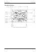
External components
Screw terminals
Ethernet connector
External power connector
LEDs
Ethernet connector LEDS
Factory reset button
Signal connections
Analog input
Floating voltage source
Channel-Gain queue
Analog output
External clock I/O
Digital I/O
Pull-up/down configuration
Trigger input
Counter input
Power output
Ground
Mechanical drawings
DIN-rail compatible
Specifications
Analog input
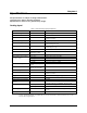
Accuracy
Analog input DC voltage measurement accuracy
Noise performance
Settling time
Analog output
Analog input/output calibration
Digital input/output
External trigger
External clock input/output
Counter
Memory
Power
Network
Ethernet connection
Network interface
Network factory default settings
Network security
LED displays and the factory reset button
Environmental
Mechanical
Screw terminal connector
Declaration of Conformity
E-
1608 Us
er
's Gui
de
Functi
onal D
etai
ls
17
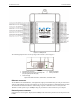
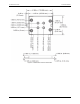
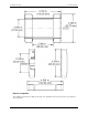
Mecha
nical drawings
Figure
8. E-
1608
device c
ircuit
board di
mensions
1
...
...
15
16
17
18
19
...
...
29