
User Guide
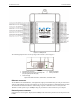
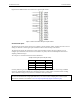
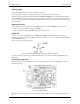
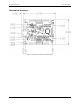
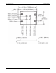
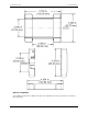
Table Of Contents
- About this User's Guide
- Introducing the E-1608
- Installing the E-1608
- Functional Details
- Specifications
- Declaration of Conformity

E-1608 User's Guide Functional Details
15
Analog output
Two 16-bit analog outputs are available at AOUT0 and AOUT1.
Each analog output channel has an output range of ±10 V. Throughput is system-dependent.
The D/A is software-paced. Each 16-bit analog output (
AOUT0 and AOUT1) can be updated simultaneously at
rates from 1000 S/s to 5000 S/s. This is the typical throughput when the device and host are both hard-wired to
the same local network. Typical throughput is not guaranteed if a wireless connection is involved or data is sent
over the Internet.
External clock I/O
The E-1608 provides one external clock input (AICKI) and one clock output (AICKO) for analog inputs.
You can connect an external clock signal to
AICKI.
When using the internal clock,
AICKO outputs the ADC scan clock.
Digital I/O
You can connect up to eight digital I/O lines to DIO0 through DIO7. Each digital channel is individually
configurable for input or output. The digital I/O terminals can detect the state of any TTL-level input and offer .
advanced BiCMOS output.
Refer to the schematic shown in Figure 5.
Figure 5. Schematic showing switch detection by digital channel DIO0
If you set the switch to the +5 V input, DIO0 reads TRUE (1). If you move the switch to GND, DIO0 reads
FALSE (0).
Pull-up/down configuration
Unconnected inputs are pulled high by default to 5 V through 47 kΩ resistors via jumper
W3 on the circuit
board (see Figure 6).
1
W3 pull-up/pull-down jumper
Figure 6. W3 jumper location
The pull-up/pull-down voltage is common to all 47 kΩ resistors. Jumper W3 is configured by default for pull-
up.