
User Guide
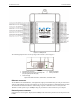
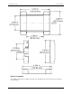
Table Of Contents
- About this User's Guide
- Introducing the E-1608
- Installing the E-1608
- Functional Details
- Specifications
- Declaration of Conformity

E-1608 User's Guide Functional Details
13
LEDs
The Power LED is steady green when external power between 3.3 V to 5.9 V is supplied to the E-1608.
The
Power LED turns off when:
power is not supplied by the external supply (make sure that the supply is fully connected to the power
connector)
the input power is outside of the specified voltage range of the external supply (3.3 V to 5.9 V ), causing
a
p
ower fault
The E-1608 has an onboard voltage supervisory circuit that monitors the 5 V external power supply.
The
Activity LED is on when there is a valid host connection, and blinks when a command is received or an
analog input scan is running.
Ethernet connector LEDS
The green Link/activity LED on the lower left of the Ethernet connector is on when there is a valid Ethernet
link, and blinks when network activity is detected.
The yellow
Speed LED on the lower right of the Ethernet connector is on when the transmission speed is
100 Mbps, and off when the transmission speed is 10 Mbps or there is no link.
Factory reset button
Use the factory reset button to reset network configuration settings to the factory default values.
Refer to
Restoring factory default network settings on page 10 to learn about resetting these values.
Signal connections
Analog input
You can configure the analog inputs for SE or DIFF mode. The input voltage range is software selectable for
±10 V, ±5 V, ±2 V, or ±1 V.
With SE mode, connect up to eight inputs to
CH0x to CH3x. SE mode requires two wires:
Connect one wire to the signal you want to measure (
CH#x).
Connect one wire to the analog ground reference (
AGND).
With DIFF mode, connect up to four differential inputs to
CH0H/CH0L to CH3H/CH3L. DIFF mode requires
two wires plus a ground reference:
Connect one wire to the high/positive signal (
CHxH).
Connect one wire to the low/negative signal (
CHxL).
Connect one wire to the analog ground reference (
AGND).
Floating voltage source
When connecting DIFF voltage inputs to a floating voltage source, make sure the DIFF input channel has a DC
return path to ground. To create this path, connect a resistor from each low channel input to an AGND pin. A
value of approximately 100 kΩ can be used for most applications.
Leave unused input channels either floating or tied to an AGND terminal. Source impedances should be kept as
small as possible to avoid settling time and accuracy errors.