E-1608 Ethernet-based High-speed Multifunction DAQ User's Guide Document Revision 2A April 2016
Trademark and Copyright Information Measurement Computing Corporation, InstaCal, Universal Library, and the Measurement Computing logo are either trademarks or registered trademarks of Measurement Computing Corporation. Refer to the Copyrights & Trademarks section on mccdaq.com/legal for more information about Measurement Computing trademarks. Other product and company names mentioned herein are trademarks or trade names of their respective companies. © 2016 Measurement Computing Corporation.
Table of Contents Preface About this User's Guide ....................................................................................................................... 5 What you will learn from this user's guide ......................................................................................................... 5 Conventions in this user's guide .........................................................................................................................
E-1608 User's Guide Analog input DC voltage measurement accuracy ............................................................................................................21 Noise performance ...........................................................................................................................................................21 Settling time .................................................................................................................................................
Preface About this User's Guide What you will learn from this user's guide This user's guide describes the Measurement Computing E-1608 data acquisition device and lists device specifications. Conventions in this user's guide For more information about … Text presented in a box signifies additional information and helpful hints related to the subject matter you are reading.
Chapter 1 Introducing the E-1608 The E-1608 is compatible with both TCP/IP (IPv4 only) and user datagram protocol (UDP) network protocols.
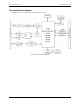
E-1608 User's Guide Introducing the E-1608 Functional block diagram E-1608 functions are illustrated in the block diagram shown here. Figure 1.
Chapter 2 Installing the E-1608 Unpacking As with any electronic device, you should take care while handling to avoid damage from static electricity. Before removing the device from its packaging, ground yourself using a wrist strap or by simply touching the computer chassis or other grounded object to eliminate any stored static charge. Contact us immediately if any components are missing or damaged. Installing the software Refer to the MCC DAQ Quick Start for instructions on installing the software.
E-1608 User's Guide Installing the E-1608 Configuring network settings The following E-1608 network settings are software-selectable. Only one user at a time can connect to the E-1608 to configure network options on the device. For typical local networks, the default settings are recommended.
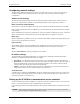
E-1608 User's Guide Installing the E-1608 1. Assuming you have successfully connected to a local network, determine the IP address of the device. If the address was assigned by DHCP, it is recommended you change it to a static address by setting the default address to the address assigned and setting the device network configuration to static. 2. Configure the firewall/router to forward incoming traffic to the following ports to the IP address assigned to the device: o o o 3.
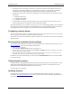
Chapter 3 Functional Details Analog input modes The E-1608 can acquire analog input data in two basic modes – software paced and hardware paced. Software paced You can acquire one analog sample at a time in software-paced mode. You initiate the A/D conversion with a software command. The analog value is converted to digital data and returned to the computer. Repeat this procedure until you have the total number of samples that you want.
E-1608 User's Guide Functional Details Figure 2. E-1608 pinout The remaining components are on the top edge of the enclosure; refer to Figure 3: 1 2 3 External power connector Ethernet connector with green Link/activity LED (left) and yellow Speed LED (right) Power LED (top) 4 5 Activity LED (bottom) Factory reset button Figure 3. E-1608 connectors, reset button, and status LEDs Ethernet connector The E-1608 has one 10/100 BASE-T, auto-negotiation, high-speed communication port.
E-1608 User's Guide Functional Details LEDs The Power LED is steady green when external power between 3.3 V to 5.9 V is supplied to the E-1608. The Power LED turns off when: power is not supplied by the external supply (make sure that the supply is fully connected to the power connector) the input power is outside of the specified voltage range of the external supply (3.3 V to 5.
E-1608 User's Guide Functional Details Figure 4 shows DIFF channels 0-3 connected to a ground path resistor. Figure 4. DIFF connections with ground path resistor Channel-Gain queue The channel-gain queue feature allows you to configure a list of channels, modes, and gains for each scan. The settings are stored in a channel-gain queue list that is written to local memory on the device. The channel-gain queue list contains one or more channel numbers, modes, and range settings.
E-1608 User's Guide Functional Details Analog output Two 16-bit analog outputs are available at AOUT0 and AOUT1. Each analog output channel has an output range of ±10 V. Throughput is system-dependent. The D/A is software-paced. Each 16-bit analog output (AOUT0 and AOUT1) can be updated simultaneously at rates from 1000 S/s to 5000 S/s. This is the typical throughput when the device and host are both hard-wired to the same local network.
E-1608 User's Guide Functional Details Figure 7 shows the jumper configured for pull-up and pull-down. Caution! The discharge of static electricity can damage some electronic components. Before touching the board, ground yourself using a wrist strap or touch the computer chassis or other grounded object to eliminate any stored static charge. Figure 7.
E-1608 User's Guide Functional Details Mechanical drawings Figure 8.
E-1608 User's Guide Functional Details Figure 9.
E-1608 User's Guide Functional Details Figure 10. E-1608 top enclosure dimensions DIN-rail compatible The E-1608can be mounted on a DIN rail using the ACC-205 DIN-rail accessory kit. Refer to our website for more information.
Chapter 4 Specifications All specifications are subject to change without notice. Typical for 25 °C unless otherwise specified. Specifications in italic text are guaranteed by design. Analog input Table 1.
E-1608 User's Guide Specifications Accuracy Analog input DC voltage measurement accuracy Table 2. DC Accuracy components and specifications. All values are (±) Range Gain error (% of reading) Offset error (µV) INL error (% of range) Absolute accuracy at Full Scale (µV) ±10 V ±5 V ±2 V ±1 V 0.024 0.024 0.024 0.024 915 686 336 245 0.0076 0.0076 0.0076 0.0076 4075 2266 968 561 Gain temperature coefficient (% reading/°C) Offset temperature coefficient (µV/°C) 0.0014 0.0014 0.0014 0.
E-1608 User's Guide Parameter Specifications Condition Specification Software paced DC DACs cleared to uncalibrated zero-scale: 0 V, ±50 mV unless the alarm function is enabled for the output (Note 3) Either or both outputs may be configured to go to defined values when an Ethernet connection with a host is established or lost.
E-1608 User's Guide Specifications Parameter Specification Input high voltage limit Input low voltage threshold 5.5 V absolute max 0.8 V max –0.5 V absolute min 0 V recommended min 3.8 V typ at no load 3.0 V min (IOH = –3 mA) 2.0 V min (IOH = –32 mA) 0.15 V typ at no load 0.
E-1608 User's Guide Parameter Schmitt trigger hysteresis Input high voltage threshold Input high voltage limit Input low voltage threshold Input low voltage limit Output high voltage Output low voltage Specifications Specification 1.01 V typ 0.6 V min 1.5 V max 2.43 V typ 1.9 V min 3.1 V max 5.5 V absolute max 1.42 V typ 1.0 V min 2.0 V max –0.5 V absolute min 0 V recommended min 4.4 V min (IOH = –50 µA) 3.80 V min (IOH = –8 mA) 0.1 V max (IOL = 50 µA) 0.44 V max (IOL = 8 mA) Counter Table 13.
E-1608 User's Guide Specifications Power Table 15. Power specifications Parameter Condition External power supply Supply current Quiescent current User output voltage range Available at +VO terminal User output current Available at +VO terminal Note 6: Specification 5V, 1A 330 mA typical (Note 6) 710 mA max including all external loading 4.40 V min to 5.25 V max, assumes supplied AC adapter is used 10 mA max This is the total quiescent current requirement for the device that includes the LEDs.
E-1608 User's Guide Specifications Network factory default settings Table 18. Factory default specifications Parameter Specification Factory default IP address Factory default subnet mask Factory default Gateway Factory default DHCP setting 192.168.0.101 255.255.255.0 192.168.0.1 DHCP + link-local enabled Network security Table 19.
E-1608 User's Guide Specifications Screw terminal connector Table 23. Screw terminal connector specifications Parameter Specification Connector type Wire gauge range Screw terminal 16 AWG to 30 AWG Table 24.
Declaration of Conformity According to ISO/IEC 17050-1:2010 Manufacturer: Address: Product Category: Measurement Computing Corporation 10 Commerce Way Suite 1008 Norton, MA 02766 USA Electrical equipment for measurement, control and laboratory use.
Measurement Computing Corporation 10 Commerce Way Norton, Massachusetts 02766 (508) 946-5100 Fax: (508) 946-9500 E-mail: info@mccdaq.com www.mccdaq.com NI Hungary Kft H-4031 Debrecen, Hátar út 1/A, Hungary Phone: +36 (52) 515400 Fax: +36 (52) 515414 http://hungary.ni.