USB-1608FS-Plus Analog Input and Digital I/O User's Guide Document Revision 5A November 2014 © Copyright 2014
Trademark and Copyright Information Measurement Computing Corporation, InstaCal, Universal Library, and the Measurement Computing logo are either trademarks or registered trademarks of Measurement Computing Corporation. Refer to the Copyrights & Trademarks section on mccdaq.com/legal for more information about Measurement Computing trademarks. Other product and company names mentioned herein are trademarks or trade names of their respective companies. © 2014 Measurement Computing Corporation.
Table of Contents Preface About this User's Guide ....................................................................................................................... 5 What you will learn from this user's guide ......................................................................................................... 5 Conventions in this user's guide .........................................................................................................................
USB-1608FS-Plus User's Guide External clock input/output............................................................................................................................... 19 Counter section ................................................................................................................................................. 20 Memory ........................................................................................................................................................
Preface About this User's Guide What you will learn from this user's guide This user's guide describes the Measurement Computing USB-1608FS-Plus data acquisition device and lists device specifications. Conventions in this user's guide For more information Text presented in a box signifies additional information and helpful hints related to the subject matter you are reading.
Chapter 1 Introducing the USB-1608FS-Plus The USB-1608FS-Plus is an analog input and digital I/O data acquisition device providing the following features: Eight 16-bit single-ended (SE) analog input channels Each input channel has a dedicated A/D converter for simultaneous sampling.
Chapter 2 Installing the USB-1608FS-Plus What comes with your shipment? Verify that the following hardware components are included in the shipment: Hardware USB-1608FS-Plus USB cable Software MCC DAQ CD Documentation MCC DAQ Quick Start The MCC DAQ Quick Start booklet provides an overview of the MCC DAQ software you received with the device, and includes information about installing the software. Please read this booklet completely before installing any software or hardware.
USB-1608FS-Plus User's Guide Installing the USB-1608FS-Plus If the LED turns off If communication is lost between the device and the computer, the device LED turns off. To restore communication, disconnect the USB cable from the computer and then reconnect it. This should restore communication, and the LED should turn on. Calibrating the hardware The Measurement Computing Manufacturing Test department performs the initial factory calibration.
Chapter 3 Functional Details Analog input modes The USB-1608FS-Plus can acquire analog input data in three modes – software paced, hardware paced, and BURSTIO. Software paced You can acquire one analog sample at a time in software-paced mode. You initiate the A/D conversion by calling a software command. The analog value is converted to digital data and returned to the computer. You can repeat this procedure until you have the total number of samples that you want.
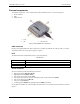
USB-1608FS-Plus User's Guide Functional Details External components The external components – screw terminal banks, LED, and USB connector –are shown in Figure 2. Screw terminals LED USB connector 1 2 Screw terminal pins 21 to 40 LED 3 4 Screw terminal pins 1 to 20 USB connector Figure 2. USB-1608FS-Plus components USB connector Receives the supplied USB cable. When connected to a computer or USB hub, the cable provides +5 V power and communication. No external power supply is required.
USB-1608FS-Plus User's Guide Functional Details Figure 3. Screw terminal pinout Signal connections Analog input You can connect up to eight analog input connections to the screw terminal containing pins 1 to 20 ( CH0 IN through CH7 IN.) Connect unused analog input terminals to ground terminals during operation. For example, if you are not using terminal 15 (CH7 IN), connect this terminal to terminal 16 (AGND). All analog input channels are configured for single-ended input mode.
USB-1608FS-Plus User's Guide Functional Details Carefully match the gain to the expected voltage range on the associated channel or an over range condition may occur. Although this condition does not damage the device, it does produce a useless full-scale reading, and can introduce a long recovery time due to saturation of the input channel. Digital I/O You can connect up to eight digital I/O lines to DIO0 through DIO7. Each digital channel is individually configurable for input or output.
USB-1608FS-Plus User's Guide Functional Details 6. Replace the top section of the housing, and fasten it to the bottom section with the three screws. For more information on digital signal connections For general information regarding digital signal connections and digital I/O techniques, refer to the Guide to Signal Connections (available on our web site at www.mccdaq.com/pdfs/DAQ-Signal-Connections.pdf).
USB-1608FS-Plus User's Guide Functional Details There are three types of errors which affect the accuracy of a measurement system: offset gain nonlinearity The primary error sources in a USB-1608FS-Plus are offset and gain. Nonlinearity is small, and is not significant as an error source with respect to offset and gain. Figure 7 shows an ideal, error-free transfer function. The typical calibrated accuracy of a USB-1608FS-Plus is range-dependent.
USB-1608FS-Plus User's Guide Functional Details The accuracy plots in Figure 9 are drawn for clarity and are not drawn to scale. Figure 9. ADC Transfer function with gain error For example, a USB-1608FS-Plus exhibits a typical calibrated gain error of ±0.04% on all ranges. For the ±10 V range, this would yield 10 V × ±0.0002 = ±4 mV. This means that at full scale, neglecting the effect of offset for the moment, the measurement would be within 4 mV of the actual value.
USB-1608FS-Plus User's Guide Functional Details Mechanical drawings Figure 11.
Chapter 4 Specifications All specifications are subject to change without notice. Typical for 25°C unless otherwise specified. Specifications in italic text are guaranteed by design. Analog input Table 1.
USB-1608FS-Plus User's Guide Specifications Table 3. Accuracy components - All values are (±) Range Gain error (% of Reading) Gain error at FS (mV) Offset (mV) ±10 V ±5 V ±2 V ±1 V 0.04 0.04 0.04 0.04 4.00 2.00 0.80 0.40 1.66 0.98 0.51 0.28 Noise performance Table 4. Noise performance Range Typical counts LSBrms ±10 V ±5 V ±2 V ±1 V 10 10 11 14 1.52 1.52 1.67 2.12 Table 4 summarizes the noise performance for the USB-1608FS-Plus.
USB-1608FS-Plus User's Guide Specifications External trigger Table 6. External trigger specifications Parameter Condition Specification Trigger source Trigger mode External digital Software-selectable TRIG_IN Edge or level sensitive: user configurable for CMOS compatible rising or falling edge, high or low level. 2 µs + 1 pacer clock cycle max 1µs min Schmitt trigger, 47 kΩ pull-down to ground 1.01 V typ 0.6 V min 1.5 V max 2.43 V typ 1.9 V min 3.1V max 5.5 V absolute max 1.42 V typ 1.0 V min 2.
USB-1608FS-Plus User's Guide Specifications Counter section Table 8. Counter specifications Parameter Specification Pin name Counter type Number of channels Input type Input source Resolution Schmitt trigger hysteresis CTR Event counter 1 Schmitt trigger, 47 kΩ pull-down to ground CTR screw terminal 32 bits 1.01 V typ 0.6 V min 1.5 V max 2.43 V typ 1.9 V min 3.1V max 5.5 V absolute max 1.42 V typ 1.0 V min 2.0 V max -0.
USB-1608FS-Plus User's Guide Specifications Power Table 11. Power specifications Parameter Condition Specification Supply current Supply current +5V power available (Note 2) USB enumeration Including DIO and SYNC output loading Connected to externally-powered root port hub or a self-powered hub < 100 mA < 500 mA 4.5 V min, 5.25 V max Output current (Note 3) 200 mA max Note 2: "Self-powered hub" refers to a USB hub with an external power supply.
USB-1608FS-Plus User's Guide Specifications Screw terminal connector and pinout Table 15. Connector specifications Parameter Specification Connector type Wire gauge range Screw terminal 16 AWG to 30 AWG Table 16.
Declaration of Conformity Manufacturer: Address: Category: Measurement Computing Corporation 10 Commerce Way Suite 1008 Norton, MA 02766 USA Electrical equipment for measurement, control and laboratory use.
Measurement Computing Corporation 10 Commerce Way Norton, Massachusetts 02766 (508) 946-5100 Fax: (508) 946-9500 E-mail: info@mccdaq.com www.mccdaq.com NI Hungary Kft H-4031 Debrecen, Hátar út 1/A, Hungary Phone: +36 (52) 515400 Fax: +36 (52) 515414 http://hungary.ni.