
MCC USB-1808X: High-Speed, High-Precision, Simultaneous USB DAQ Device - User Guide
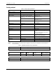
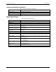
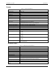
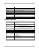
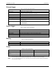
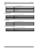
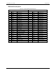
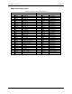

Table Of Contents
- About this User's Guide
- Introducing the USB-1808X
- Installing the USB-1808X
- Functional Details
- Specifications
- EU Declaration of Conformity

USB-1808X User's Guide Specifications
22
Counter
Table 11. Counter specifications
Parameter Specification
Terminal names
CTR0, CTR1
Number of channels
2 channels
Resolution
32-bit
Counter type
FPGA
Counter input modes
Totalize, Pulse width, Period
Input type
Schmitt trigger, 33 Ω series resistor, 47 kΩ pull-down to ground
Input source CTR0
CTR1
Scan clock source
Internal input scan clock or external input scan clock (ICLKI pin)
Trigger source ITRIG (see External trigger on page 24)
Digital pattern detection (see Pattern trigger on page 24)
Counter read clock
Internal or external input scan clock up to 200 kHz
Period/pulse width resolution
20 ns, 200 ns, 2 µs or 20 µs; software-selectable
Input high voltage
2.2 V min, 5.5 V max
Input low voltage
1.5 V max, –0.5 V min
Schmitt trigger hysteresis
0.4 V min, 1.2 V max
Input frequency
50 MHz, max
Schmitt trigger hysteresis 0.76 V typ
0.4 V min
1.2 V max
Input high voltage threshold
1.74 V typ
1.3 V min
2.2 V max
Input low voltage threshold 0.98 V typ
0.6 V min
1.5 V max
Input low voltage limit
–0.5 V absolute min
0 V recommended min
Quadrature inputs
Table 12. Quadrature input specifications
Parameter Specification
Terminal names
ENC0A, ENC0B, ENC0Z; ENC1A, ENC1B, ENC1Z
Number of encoders
2
Signals per encoder
A, B and Z
Resolution
20 ns
Maximum frequency
50 MHz
Minimum pulse width
10 ns
De-bounce function
None
Scan clock source
Internal input scan clock or external input scan clock (ICLKI pin)
Trigger source ITRIG (see External trigger on page 24)
Digital pattern detection (see Pattern trigger on page 24)
Input high voltage
2.2 V min, 5.5 V max
Input low voltage
1.5 V max, –0.5 V min
Absolute maximum input
voltage
5.5 V