USB-1808X Eight-Channel Simultaneous-Sampling Multifunction Device User's Guide May 2019.
Trademark and Copyright Information Measurement Computing Corporation, InstaCal, Universal Library, and the Measurement Computing logo are either trademarks or registered trademarks of Measurement Computing Corporation. Refer to the Copyrights & Trademarks section on mccdaq.com/legal for more information about Measurement Computing trademarks. Other product and company names mentioned herein are trademarks or trade names of their respective companies. © 2019 Measurement Computing Corporation.
Table of Contents Preface About this User's Guide ....................................................................................................................... 5 What you will learn from this user's guide ......................................................................................................... 5 Conventions in this user's guide .........................................................................................................................
USB-1808X User's Guide Noise performance ...........................................................................................................................................................19 Analog output ................................................................................................................................................... 20 Analog input/output calibration ..................................................................................................................
Preface About this User's Guide What you will learn from this user's guide This user's guide describes the Measurement Computing USB-1808X data acquisition device and lists device specifications. Conventions in this user's guide For more information Text presented in a box signifies additional information and helpful hints related to the subject matter you are reading.
Chapter 1 Introducing the USB-1808X The USB-1808X is a multifunction data acquisition device providing the following features: Eight 18-bit simultaneous-sampling differential (DIFF) or single-ended (SE) analog input channels – software-selectable per channel as DIFF or SE Sample rate of 200 kS/s per channel maximum Analog input ranges of ±10 V, ±5 V, 0 V to 10 V, and 0 V to 5 V – software-selectable per channel Two 16-bit analog outputs Four individually-configurable digital I/O chan
Chapter 2 Installing the USB-1808X Unpacking As with any electronic device, you should take care while handling to avoid damage from static electricity. Before removing the device from its packaging, ground yourself using a wrist strap or by simply touching the computer chassis or other grounded object to eliminate any stored static charge. Contact us immediately if any components are missing or damaged.
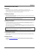
Chapter 3 Functional Details External components The USB-1808X has the following external components (see Figure 2 through Figure 4 on pgs. 9-10): USB connector LEDs Screw terminals USB connector The USB connector provides +5 V power and communication. No external power supply is required.
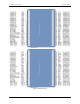
USB-1808X User's Guide Functional Details Figure 2. DIFF mode pinout Figure 3.
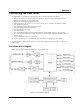
USB-1808X User's Guide Functional Details LEDs The USB-1808X has two LED indicators that indicate the status of power and data. The LEDs are stacked one above the other, as shown in Figure 4. The Status LED turns on when the device is detected by the computer. The Activity LED blinks when data is transferred and is off otherwise. 1 2 USB connector Status LED 3 Activity LED Figure 4. LED indicators Analog input You can configure each analog input channel for either SE or DIFF mode.
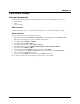
USB-1808X User's Guide Functional Details Carefully match the gain to the expected voltage range on the associated channel or an over range condition may occur. Although this condition does not damage the device, it does produce a useless full-scale reading, and can introduce a long recovery time due to saturation of the input channel. Analog output The two 16-bit analog outputs (AOUT0 and AOUT1) can be updated simultaneously at a rate of 500 kS/s per channel.
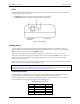
USB-1808X User's Guide 4. Functional Details Hold both the top and bottom sections together, turn the device over and rest it on the surface, then carefully remove the top section of the case to expose the circuit board. Figure 6 shows the location of the DIO jumper on the circuit board. Figure 6. Pull-up/down jumper location 5. Configure the DIO jumper for pull-up or pull-down, as shown in Figure 7. Figure 7. Pull-up/down jumper configuration 6.
USB-1808X User's Guide Functional Details Typically, when data is acquired with no counter operation options set, the count of each counter channel is set to 0 and latched at the beginning of the acquisition. When counter options are set the counters can concurrently monitor time periods, frequencies, pulses, and other event-driven incremental occurrences directly from pulse-generators, limit switches, proximity switches, and magnetic pick-ups.
USB-1808X User's Guide Functional Details Encoder input operations can be paced by the internal clock or by an external clock (ICLKI – refer to Clock I/O on page 15). They can be initiated by a digital trigger (Digital triggering on page 15) or a pattern trigger (Pattern triggering on page 15). Refer to Synchronous I/O – mixing analog, digital, and counter scanning on page 15 for information on running quadrature encoder scans at the same time as other subsystem scans.
USB-1808X User's Guide Functional Details Synchronous I/O – mixing analog, digital, and counter scanning The USB-1808X can read analog, digital, and counter inputs, and generate up to two analog outputs and one digital pattern output at the same time. Digital and counter inputs do not affect the overall A/D rate because these inputs use no time slot in the scanning sequencer. For example, one analog input channel can be scanned at the full 200 kS/s A/D rate along with digital and counter input channels.
USB-1808X User's Guide Functional Details In Figure 10 all mask bits are excluded except bit 3. The result of this operation is that only bit 3 is included in the pattern to detect. Figure 10. Trigger mask with some bits excluded Ground The analog ground (AGND) terminals provide a common ground for all analog channels. The digital ground (GND) terminals provide a common ground for the digital, trigger, counter, and encoder terminals. Power output The +VO terminal can output up to 10 mA maximum.
USB-1808X User's Guide Functional Details Mechanical drawings Figure 11.
Chapter 4 Specifications All specifications are subject to change without notice. Typical for 25 °C unless otherwise specified. Specifications in italic text are guaranteed by design. Analog input Table 1.
USB-1808X User's Guide Specifications Accuracy Analog input DC voltage measurement accuracy Table 2. DC accuracy components and specifications. All values are (±) Range Gain error (% of reading) Offset error (mV) INL error (% of range) Absolute accuracy at Full Scale (mV) Gain temperature coefficient (% reading/°C) Offset temperature coefficient (µV/°C) ±10 V ±5 V 0 V to 10 V 0 V to 5 V 0.020 0.020 0.020 0.020 1.5 1.0 1.5 1.0 0.00076 0.00057 0.00028 0.00014 3.576 2.028 3.528 2.007 0.00023 0.
USB-1808X User's Guide Specifications Analog output Table 5.
USB-1808X User's Guide Specifications Analog input/output calibration Table 9. Analog I/O calibration specifications Parameter Specification Warm-up time Calibration method Calibration interval 15 minutes recommended min Factory calibration 1 year Digital input/output Table 10.
USB-1808X User's Guide Specifications Counter Table 11.
USB-1808X User's Guide Specifications Timer Table 13. Timer specifications Parameter Specification Terminal name Timer type Output value Trigger source Internal clock frequency Register widths High pulse width Low pulse width Output high voltage TMR0, TMR1 PWM output with count, period, delay, and pulse width registers Default state is idle low with pulses high, software-selectable output invert OTRIG (see External trigger on page 24) 100 MHz 32-bit 10 ns min 10 ns min 4.4 V min (IOH = –50 µA) 3.
USB-1808X User's Guide Specifications External trigger Table 15. External trigger specifications Parameter Specification Trigger source Trigger mode ITRIG for inputs, OTRIG for outputs Software programmable for edge or level sensitive, rising or falling edge, high or low level. Power on default is edge sensitive, rising edge. 1 µs + 1 clock cycle max 100 ns min Schmitt trigger, 33 Ω series resistor and 49.9 kΩ pull-down to ground 0.4 V to 1.2 V 2.2 V min 5.5 V absolute max 1.5 V max –0.
USB-1808X User's Guide Specifications USB Table 19. USB specifications Parameter Specification USB device type Device compatibility USB cable type USB 2.0 (high-speed) USB 1.1, USB 2.0, USB 3.0 A-B cable, UL type AWM 2725 or equivalent. (Min 24 AWG VBUS/GND, min 28 AWG D+/D–) 3 m (9.84 ft) max USB cable length Environmental Table 20.
USB-1808X User's Guide Specifications Differential mode pinout Table 23.
USB-1808X User's Guide Specifications Single-ended mode pinout Table 24.
EU Declaration of Conformity According to ISO/IEC 17050-1:2010 Manufacturer: Address: Product Category: Date and Place of Issue: Test Report Number: Measurement Computing Corporation 10 Commerce Way Norton, MA 02766 USA Electrical equipment for measurement, control and laboratory use. March 23, 2017, Norton, Massachusetts USA EMI6990.
Measurement Computing Corporation 10 Commerce Way Norton, Massachusetts 02766 (508) 946-5100 Fax: (508) 946-9500 E-mail: info@mccdaq.com www.mccdaq.com NI Hungary Kft H-4031 Debrecen, Hátar út 1/A, Hungary Phone: +36 (52) 515400 Fax: +36 (52) 515414 http://hungary.ni.