
MCC USB-1808X: High-Speed, High-Precision, Simultaneous USB DAQ Device - Datasheet
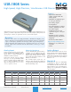
Table Of Contents

Measurement Computing (508) 946-5100
5
info@mccdaq.com mccdaq.com
USB-1808 Series
Specifications
Digital I/O transfer rate (synchronous)
USB-1808: 0.023 Hz to 50 kHz input, 125 kHz output, based on the internal
clock speed of 100 MHz
USB-1808X: 0.023 Hz to 200 kHz input, 500 kHz output, based on the internal
clock speed of 100 MHz
Scan clock source for input: Internal input scan clock or external input scan
clock (ICLKI pin)
Scan clock source for input: Internal output scan clock or external output scan
clock (OCLKI pin)
Trigger source
ITRIG for inputs, OTRIG for outputs (see External Trigger on page 6)
Digital pattern detection (see Pattern Trigger on page 6)
Input high voltage: 2.0 V min, 5.5 V absolute max
Input low voltage: 0.8 V max, –0.5 V absolute min, 0 V recommended min
Output high voltage: 4.4 V min (IOH = –50 µA), 3.76 V min (IOH = –2.5 mA)
Output low voltage 0.1 V max (IOL = 50 µA), 0.44 V max (IOL = 2.5 mA)
Output current: ±2.5 mA max
Counter
Terminal names: CTR0, CTR1
Number of channels: 2 channels
Resolution : 32-bit
Counter type: FPGA
Counter input modes: Totalize, Pulse width, Period
Input type : Schmitt trigger, 33 Ω series resistor, 47 kΩ pull-down to ground
Input source: CTR0, CTR1
Scan clock source: Internal input scan clock or external input scan clock (ICLKI pin)
Trigger source
ITRIG (see External Trigger on page 6)
Digital pattern detection (see Pattern Trigger on page 6)
Counter read clock: Internal or external input scan clock up to 200 kHz
Period/pulse width resolution: 20 ns, 200 ns, 2 µs or 20 µs; software-selectable
Input high voltage: 2.2 V min, 5.5 V max
Input low voltage: 1.5 V max, –0.5 V min
Schmitt trigger hysteresis: 0.4 V min, 1.2 V max
Input frequency: 50 MHz, max
Schmitt trigger hysteresis: 0.76 V typ, 0.4 V min, 1.2 V max
Input high voltage threshold: 1.74 V typ, 1.3 V min, 2.2 V max
Input low voltage threshold: 0.98 V typ, 0.6 V min, 1.5 V max
Input low voltage limit: –0.5 V absolute min, 0 V recommended min
Quadrature Inputs
Terminal names: ENC0A, ENC0B, ENC0Z; ENC1A, ENC1B, ENC1Z
Number of encoders: 2
Signals per encoder: A, B and Z
Resolution : 20 ns
Maximum frequency: 50 MHz
Minimum pulse width: 10 ns
De-bounce function: None
Scan clock source: Internal input scan clock or external input scan clock (ICLKI pin)
Trigger source
ITRIG (see External Trigger on page 6)
Digital pattern detection (see Pattern Trigger on page 6)
Input high voltage: 2.2 V min, 5.5 V max
Input low voltage: 1.5 V max, –0.5 V min
Absolute maximum input voltage: 5.5 V
Timer
Terminal name: TMR0, TMR1
Timer type: PWM output with count, period, delay, and pulse width registers
Output value: Default state is idle low with pulses high, software-selectable
output invert
Trigger source: OTRIG (see External Trigger on page 6)
Internal clock frequency: 100 MHz
Register widths: 32-bit
High pulse width: 10 ns min
Low pulse width: 10 ns min
Output high voltage: 4.4 V min (IOH = –50 µA), 3.76 V min (IOH = –2.5 mA)
Output low voltage: 0.1 V max (IOL = 50 µA), 0.44 V max (IOL = 2.5 mA)
Output current: ±2.5 mA max
Noise Performance
For the peak-to-peak noise distribution test, a differential input channel is con-
nected to AGND at the input terminal block, and 32,000 samples are acquired
at the maximum rate available at each setting.
Range Counts LSBrms
±10 V 11.6 1.77
±5 V 18.0 2.73
0 V to 10 V 23.3 3.54
0 V to 5 V 36.1 5.47
Analog Output
Number of channels: 2
Resolution : 16 bits
Output ranges (calibrated): ±10 V
Output transient
Host computer is reset, powered on, suspended, or a reset command is
issued to the device
Duration: 5 ms
Amplitude: 2 V p-p
Powered off from 0 V output
Duration: 20 ms
Amplitude: 5 V p-p
Differential nonlinearity: ±0.25 LSB typ, ±1 LSB max
Output current (AOUTx pins): ±3.5 mA max
Output short-circuit protection (single AOUTx channel connected to AGND:
Unlimited duration
Output coupling: DC
Power on and reset state (DACs cleared to zero-scale): 0 V, ±50 mV
Output noise: 100 µVrms
Trigger source
OTRIG (see External Trigger on page 6)
Digital pattern detection (see Pattern Trigger on page 6)
Scan clock source: Internal output scan clock or external output scan clock
(OCLKI pin)
Output update rate
USB-1808: 0.023 Hz to 125 kHz per channel
USB-1808X: 0.023 Hz to 500 kHz per channel
Slew rate: 15 V/µS
Throughput
Software paced: 33 S/s to 8,000 S/s typ, system-dependent
Hardware paced
USB-1808: 250 kS/s max, system-dependent
USB-1808X: 1,000 kS/s max, system-dependent
Calibrated Absolute Accuracy
±10 V range: ±16 LSB
Calibrated Absolute Accuracy Components
Range: ±10 V
% of reading: 0.0183
Offset: ±1.831 mV
Offset tempco: ±4.7 µV/°C
Gain tempco: 9.4 ppm of range/°C
Relative Accuracy (±LSB)
±10 V range: 1.0 INL
Analog Input/Output Calibration
Warm-up time: 15 minutes recommended min
Calibration method: Factory calibration
Calibration interval: 1 year
Digital Input/Output
Digital type: CMOS
Number of I/O: 4
Configuration: Each bit may be configured as input (power on default) or output
Pull-up configuration: The port has 47 kΩ resistors configurable as pull-up or
pull-down (default) via internal jumper (DIO).
Digital I/O transfer rate (system paced, asynchronous): 33 to 8,000 port reads/
writes or single bit reads/writes per second typ, system dependent.