USB-234 Analog and Digital I/O User's Guide January 2019.
Trademark and Copyright Information Measurement Computing Corporation, InstaCal, Universal Library, and the Measurement Computing logo are either trademarks or registered trademarks of Measurement Computing Corporation. Refer to the Copyrights & Trademarks section on mccdaq.com/legal for more information about Measurement Computing trademarks. Other product and company names mentioned herein are trademarks or trade names of their respective companies. © 2019 Measurement Computing Corporation.
Table of Contents Preface About this User's Guide ....................................................................................................................... 5 What you will learn from this user's guide ......................................................................................................... 5 Conventions in this user's guide .........................................................................................................................
USB-234 User's Guide Environmental .................................................................................................................................................. 26 Mechanical ....................................................................................................................................................... 26 Screw terminal connector .................................................................................................................................
Preface About this User's Guide What you will learn from this user's guide This user's guide describes the Measurement Computing USB-234 data acquisition device and lists device specifications. Conventions in this user's guide For more information Text presented in a box signifies additional information related to the subject matter. Caution! Shaded caution statements present information to help you avoid injuring yourself and others, damaging your hardware, or losing your data.
Chapter 1 Introducing the USB-234 The USB-234 is a high-speed data acquisition USB board supported under the Windows® operating system. The USB-234 is a USB 2.0 high speed device that is compatible with USB 3.0 ports. The device is also compatible with USB 1.1 ports but use with this older hardware is not recommended due to longer initialization times that can occur when the USB-234 is connected through USB 1.1 ports or hubs.
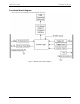
USB-234 User's Guide Introducing the USB-234 Functional block diagram Device functions are illustrated in the block diagram shown here. Figure 1.
Chapter 2 Installing the USB-234 Unpacking As with any electronic device, you should take care while handling to avoid damage from static electricity. Before removing the device from its packaging, ground yourself using a wrist strap or by simply touching the computer chassis or other grounded object to eliminate any stored static charge. If any components are missing or damaged, contact us immediately using one of the following methods: Knowledgebase: kb.mccdaq.com Tech support form: www.mccdaq.
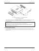
USB-234 User's Guide Installing the USB-234 1 Screw terminal connector plugs 2 Hi-Speed Micro -USB cable Figure 2. Setting up a USB-234 When connected for the first time, a Found New Hardware dialog box opens when the operating system detects the device. When the dialog closes, the installation is complete. The LED turns on after the device is successfully installed. If the LED turns off or blinks If the LED turns off, the device is either not fully connected or is in suspend mode.
Chapter 3 Functional Details Analog input acquisition modes The USB-234 can acquire analog input data in two different modes – software paced and hardware paced. Software paced mode You can acquire one analog sample at a time in software paced mode. You initiate the A/D conversion with a software command. The analog value is converted to digital and returned to the computer. You can repeat this procedure until you have the total number of samples that you want.
USB-234 User's Guide Functional Details External components The external components on the USB-234 are shown in Figure 3. 1 2 Screw terminal pins 1 to 16 Screw terminal pins 17 to 32 3 4 LED Indicator USB connector Figure 3.
USB-234 User's Guide Functional Details Figure 4.
USB-234 User's Guide Functional Details Figure 5. USB-234 single-ended pinout USB connector The Micro-USB connector provides +5 V power and communication. No external power supply is required. LED indicator The table below lists the device status indicated by the LED: LED State Device Status Off On, not blinking Blinking Device is not connected or is in suspend mode. Device is connected and functioning normally.
USB-234 User's Guide Functional Details Signal connections Analog input You can connect up to eight single-ended inputs or up to four differential inputs to screw terminals CH0H/CH0L through CH3H/CH3L. The input voltage range is ±10 V. Figure 6 shows the USB-234 analog input circuitry. Figure 6. USB-234 analog input circuitry The main analog input circuitry blocks are as follows: MUX—The multiplexer (MUX) routes one AI channel at a time to the mode selector multiplexer (DIFF/SE MUX).
USB-234 User's Guide Functional Details Differential configuration When configured for differential input mode, the input signal is measured with respect to the low input and delivered through three wires: Connect the wire carrying the signal to be measured to CHxH Connect the wire carrying the reference signal to CHxL Connect the third wire to AGND. The differential mode pinout is shown in Figure 4 on page 12.
USB-234 User's Guide Functional Details Analog output Figure 8 shows the USB-234 analog output circuitry. Figure 8. USB-234 analog output circuitry The main analog output circuitry blocks are as follows: Protection – The protection circuit prevents damage of the buffers in case of a short circuit or an overvoltage condition. Buffer – The buffer amplifies the analog signal to the ±10 V range and ensures the driving capability for the external load.
USB-234 User's Guide Functional Details Figure 9. USB-234 analog output connection diagram Power-on state The AO circuitry exhibits a short glitch when the device is powered on and when the DAQ device exits suspend mode. After power-up, the AO circuitry is reset to 0 V. AO range The AO range is ± 10 V. Minimizing glitches on the output signal When using a DAC to generate a waveform, you may observe glitches on the output signal.
USB-234 User's Guide Functional Details Digital I/O You can connect up to eight digital I/O lines to DIO0 through DIO7. GND is the ground-reference signal for digital I/O. Each digital I/O line is bit-configurable as input or output. Digital input voltage ranges from 0 V to 5 V are permitted, with thresholds of 0.8 V (low) and 2.3 V (high). Each DIO channel can sink up to 4 mA for direct drive applications when used as an output. All digital I/O updates and samples are software-paced.
USB-234 User's Guide Functional Details Trigger input The TRIG terminal is an external digital trigger input. The trigger mode is software-selectable for rising edge- or falling edge detection. Counter input The CTR terminal is a 32-bit counter that can count rising edges. Edges can only be counted up from 0. Counting down is not supported – you cannot set the initial count to 100 and count down to 99, 98, 97. +VO power source Figure 11 shows the +VO power source circuitry of the USB-234. Figure 11.
USB-234 User's Guide Functional Details Figure 12. Connecting the +VO power source load The + 5 V power is always enabled and the voltage is present at the +VO terminal when the device is in active mode. The +5 V power source is not available for about one second after the device is first connected to the USB connector or when the device is in suspend mode. Ground The analog ground (AGND) terminals provide a common ground for all analog channels.
USB-234 User's Guide Functional Details Mechanical drawings Figure 13.
Chapter 4 Specifications All specifications are subject to change without notice. Typical for 25 °C unless otherwise specified. Specifications in italic text are guaranteed by design. Analog input Table 1.
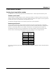
USB-234 User's Guide Specifications Analog output Table 3. Analog output specifications Parameter Resolution Output range Number of channels Update rate Trigger sources Output current drive Condition Specification 16 bits, 1 in 65,536 ±10 V 2 5 kS/s simultaneous per channel max, hardware-paced Software, TRIG ±5 mA Hardware paced Short circuit current ±11 mA Slew rate Output impedance 3 V/µs 0.2 Ω 8.
USB-234 User's Guide Specifications Digital input Table 5. Digital input specifications Parameter Condition Specification Input voltage range Power on Power off 0 V to 5 V 0 V to 3.3 V (Note 1) ±20 V on two lines per port (maximum of five lines for all ports) for up to 24 hours 2.3 V min 0.8 V max 0.8 mA max 4.5 mA max Input voltage protection Input high voltage Input low voltage Input leakage current At 3.3 V At 5 V Note 1: Do not leave a voltage above 3.
USB-234 User's Guide Specifications Memory Table 8 Memory specifications Parameter Specification Data FIFO Non-volatile memory 2,047 samples (4096 bytes) Up to 256 kB microcontroller integrated Flash 2 kB microcontroller integrated EEPROM) Power requirements Table 9. Power specifications Parameter Specification From USB Idle USB current 4.50 to 5.25 VDC (Note 2) 165 mA Maximum load USB current <500 mA (Note 3) Note 2: A typical bus-powered hub provides 100 mA on its USB lines.
USB-234 User's Guide Specifications Environmental Table 12. Environmental specifications (Indoor use only) Parameter Specification Operating temperature range Storage temperature range Operating humidity range Storage humidity range Pollution degree (IEC 60664) Maximum altitude 0 °C to 45 C –40 °C to 85 °C 5% to 95% RH, non-condensing 5% to 90% RH, non-condensing 2 2,000 m Mechanical Table 13.
USB-234 User's Guide Specifications Screw terminal pinout Differential mode pinout Do not connect to terminal block pins labeled NC. Table 15.
EU Declaration of Conformity According to ISO/IEC 17050-1:2010 Manufacturer: Address: Product Category: Date and Place of Issue: Test Report Number: Measurement Computing Corporation 10 Commerce Way Norton, MA 02766 USA Electrical equipment for measurement, control and laboratory use.
Measurement Computing Corporation 10 Commerce Way Norton, Massachusetts 02766 (508) 946-5100 Fax: (508) 946-9500 E-mail: info@mccdaq.com www.mccdaq.com NI Hungary Kft H-4031 Debrecen, Hátar út 1/A, Hungary Phone: +36 (52) 515400 Fax: +36 (52) 515414 http://hungary.ni.