MCC USB-200 Series Single Gain Multifunction USB DAQ Devices (USB-205) - User Guide
Manuals
Brands
Digilent Manuals
IO Expansion & ADCs
MCC USB-205 Single Gain Multifunction USB DAQ Devices
11
12
13
14
15
16
17
18
19
20
Table Of Contents
About this User's Guide
What you will learn from this user's guide
Conventions in this user's guide
Where to find more information
Introducing the USB-205
Functional block diagram
Installing the USB-205
Unpacking
Installing the software
Installing the hardware
Installing on a Windows platform
Calibrating the hardware
Factory calibration
Field calibration
Functional Details
Analog input acquisition modes
Software paced mode
Hardware paced mode
External components
Screw terminals
USB connector
LED indicators
Signal connections
Analog input
External clock I/O
Analog output
Digital I/O
Pull-up/down jumper W4
Trigger input
Counter input
Voltage output
Ground
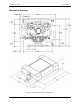
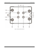
Mechanical drawings
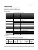
Specifications
Analog input
Accuracy
Analog input DC voltage measurement accuracy
Noise performance
Analog input calibration
Analog output
Digital input/output
External digital trigger
External pacer input/output
Counter
Memory
Power
USB specifications
Environmental
Mechanical
Screw terminal connector
USB
-
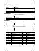
205 User's Guide
Functional D
etails
13
Figure
8.
Housi
ng bottom dim
ensions
1
...
...
11
12
13
14
15
...
...
21