
Manual
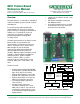

8051 Reference Manual Digilent, Inc.
www.digilentinc.com page 4 of 4
Copyright Digilent, Inc. All rights reserved. Other product and company names mentioned may be trademarks of their respective owners.
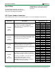
connector Description
8051 Trainer 8 Pins Headers
Pin
Function
J5 and J7
Dip Switch Connectors
These pins provide access to switches. It provides
logical zero or one (0 or 5v) for the chip or any
external devices.
1
Switch 1 of dipswitch
2
Switch 2 of dipswitch
3
Switch 3 of dip
switch
4
Switch 4 of dipswitch
5
Switch 5 of dipswitch
6
Switch 6 of dipswitch
7
Switch 7 of dipswitch
8
Switch 8 of dipswitch
J6 and J8
LED
Connectors
These pins provide access to the LEDs. Each LED
input is buffered via 74LS244 and there is no need
for external diver.
1
LED 1
2
LED 2
3
LED 3
4
LED 4
5
LED 5
6
LED 6
7
LED 7
8
LED 8
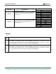
Jumpers
Jumper
Label
Function
S1
RXD of serial #1
This jumper is used to connect p1.2 to the max232 IC.
If jumper S1 is connected P1.2 should
not be externally used because P1.2 is connected to Max232 through S1. To be able to connect P1.2
to an external device you must disconnect the S1 jumper
on the board.
S2
T
XD of serial #1
This jumper is used to connect p1.3 to the max232 IC.
If jumper S2 is connected P1.3 should
not be externally used because P1.3 is connected to Max232 through S2. To be able to connect P1.3
to an external device you must disconnect the S2 jumper
on the board.