
Instruction Manual


62 www.xilinx.com XUP Virtex-II Pro Development System
UG069 (v1.0) March 8, 2005
Chapter 2: Using the System
R
.
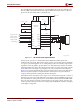
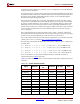
If no device is actively pulling the signal low, the pull-up resistor pulls up the signal on the
FPGA side. The gate and source of the MOS-FET are both at the same potential and the
MOS-FET is not conducting. This allows the signal on the peripheral side to be pulled up
by the pull-up resistor. So both sections of the signal are high, but at different voltage
levels.
If the FPGA actively pulls the signal low, the MOS-FET begins to conduct and pulls the
peripheral side low as well.
If the peripheral side pulls the signal low, the FPGA side is initially pulled low via the
drain-substrate diode of the MOS-FET. After the threshold is passed, the MOS-FET begins
to conduct and the signal is further pulled down via the conducting MOS-FET.
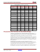
Table 2-18 identifies the PS/2 signal connections to the FPGA.
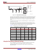
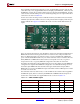
Using the Fast Ethernet Network Interface
The 10/100 Ethernet is a network protocol, defined by the IEEE 802.3 standard, which
includes a 10 Mb/s Ethernet and a 100 Mb/s Ethernet. The XUP Virtex-II Pro
Development System has been designed to support Internet connectivity using an
Ethernet connection.
Figure 2-18: PS/2 Serial Port Implementation
BSS138
BSS138
U24
R108
R107
C442
470PF
C441
GNDGNDGND
470PF
3K3
3K3
3
2
1
2
3
1
BSS138
U24
U25
KBD_DATA
KBD_CLOCK
VCC3V3
R106
2K0
R105
2K0
BIDIRECTIONAL
LEVEL
SHIFTER
L54
J12A
HZ0805E601R-00
L53 HZ0805E601R-00
STACKED_PS2_6PIN
UPPER
VCC5V0
D
D
3
0
3
0
H CHAH H CHAH
UG069_18_101804
Table 2-18: Keyboard, Mouse, and RS-232 Connections
Signal Direction FPGA Pin I/O Type Drive Slew
KBD_CLOCK I/O AG2 LVTTL 8 mA SLOW
KBD_DATA I/O AG1 LVTTL 8 mA SLOW
MOUSE_CLOCK I/O AD6 LVTTL 8 mA SLOW
MOUSE_DATA I/O AD5 LVTTL 8 mA SLOW
RS232_TX_DATA O AE7 LVCMOS25 8 mA SLOW
RS232_RX_DATA I AJ8 LVCMOS25 – –
RS232_DSR_OUT O AD10 LVCMOS25 8 mA SLOW
RS232_CTS_OUT O AE8 LVCMOS25 8 mA SLOW
RS232_RTS_IN I AK8 LVCMOS25 – –