
Instruction Manual

XUP Virtex-II Pro Development System www.xilinx.com 45
UG069 (v1.0) March 8, 2005
Using the Expansion Headers and Digilent Expansion Connectors
R
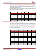
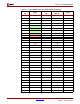
In addition to the two low-speed expansion connectors, a single 100-pin high-speed
connector is also provided. This connector provides 40 single-ended user I/Os or 34
differential pairs with additional clock resources. These signals are not shared with any
other connector. Table 2-17 provides the pinout information.
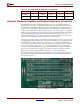
The front-mounted Digilent expansion connectors, low speed and high speed, provide the
capability of extending the JTAG-based configuration bitstream to the attached peripheral
cards if required.
For pinout information on the Digilent peripheral boards that are compatible with the XUP
Virtex-II Pro Development System, consult the Digilent Web site at:
http://www.digilentinc.com
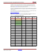
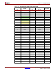
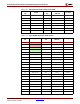
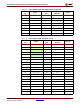
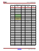
Note: In Ta ble 2- 1 0 through Ta bl e 2- 16 , the power rails available on the expansion headers and
connectors are color coded, so they can be easily located in the pinout tables.
Table 2-10: Top Expansion Header Pinout
J1
Pin
Signal
FPGA
Pin
Digilent
EXP Pin
I/O Type
1
VCC2V5 – – –
3
VCC2V5 – – –
5
VCC3V3 – J5.3 J6.3 –
7
VCC3V3 – J5.3 J6.3 –
9
VCC3V3 – J5.3 J6.3 –
11 EXP_IO_0 K2 – LVTTL
13 EXP_IO_1 L2 – LVTTL
15 EXP_IO_2 N8 – LVTTL
17 EXP_IO_3 N7 – LVTTL
19 EXP_IO_4 K4 – LVTTL
21 EXP_IO_5 K3 – LVTTL
23 EXP_IO_6 L1 – LVTTL
25 EXP_IO_7 M1 – LVTTL
27 EXP_IO_8 N6 J5.4 LVTTL
29 EXP_IO_9 N5 J5.5 LVTTL
31 EXP_IO_10 L5 J5.6 LVTTL
33 EXP_IO_11 L4 J5.7 LVTTL
35 EXP_IO_12 M2 J5.8 LVTTL
37 EXP_IO_13 N2 J5.9 LVTTL
39 EXP_IO_14 P9 J5.10 LVTTL
41 EXP_IO_15 R9 J5.11 LVTTL
43 EXP_IO_16 M4 J5.12 LVTTL