
User Manual


1-Aug-2012
28
The PS boot mode selections are shown in the table below, default setting highlighted in yellow:
Table 18 – ZedBoard Configuration Modes
Xilinx TRM
MIO[6]
MIO[5]
MIO[4]
MIO[3]
MIO[2]
Boot_Mode[4]
Boot_Mode[2]
Boot_Mode[1]
Boot_Mode[0]
Boot_Mode[3]
JTAG Mode
Cascaded
JTAG
0
Independent
JTAG
1
Boot Devices
JTAG
0
0
0
Quad-SPI
1
0
0
SD Card
1
1
0
PLL Mode
PLL Used
0
PLL
Bypassed
1
Bank Voltages
MIO Bank 500
3.3V
MIO Bank 501
1.8V
Expected configuration time using a 50MB/s QSPI flash is 250ms.
PUDC_B is pulled high on ZedBoard but can be pulled low via JP5. This active-low input enables
internal pull-ups during configuration on all SelectIO pins
A push button labeled “PROG” is connected to the EPP PROG pin, T11, and pulled up. Pushing
the button connects PROG to ground. Upon releasing the button, a re-configuration is initiated.
A blue LED, LD12, should light when the EPP DONE is asserted.
2.10.1 JTAG
As an alternative to using the onboard USB-JTAG interface, the ZedBoard provides traditional
Platform Cable JTAG connector, J15, for use with Xilinx Platform Cables and Digilent JTAG HS1
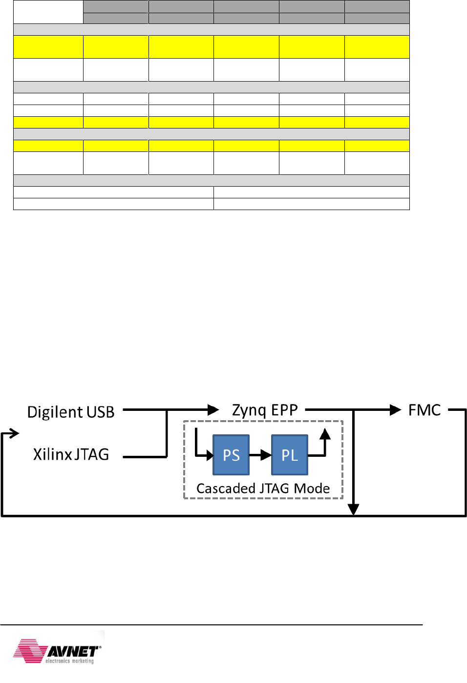
Programming Cables. The JTAG Chain is constructed as follows:
Figure 16 - ZedBoard JTAG Chain
ZedBoard automatically adds the FMC into the JTAG chain when an FMC card is plugged into
the board via the FMC-PRSNT signal.