
User Manual


21/02/2020 Pmod ToF Reference Manual [Reference.Digilentinc]
https://reference.digilentinc.com/reference/pmod/pmodtof/reference-manual?_ga=2.11378417.475818879.1582283268-1306234254.1582101049 6/9
For more details about the calibration process, see the ISL29501's Calibration Guide (https://reference.digilentinc.com/lib/exe/fetch.php?
tok=f06809&media=https%3A%2F%2Fwww.renesas.com%2Feu%2Fen%2Fwww%2Fdoc%2Fapplication-note%2Fan1983.pdf).
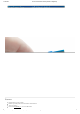
(https://reference.digilentinc.com/_detail/reference/pmod/pmodtof/txrx.png?id=reference%3Apmod%3Apmodtof%3Areference-manual)
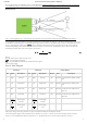
A measurement cycle of Pmod ToF is triggered by a falling edge on the sample start (SS) pin, or by the host board issuing a soft_start to
the ISL29501's command register via I2C. When performing a measurement, the chip emitter driver transmits a modulated square wave
(Tx) at a given frequency optical signal ( ) through the emitter. The received optical signal (Rx) returns with a phase shift and
attenuation depending on the distance and reflectivity of the object it bounced off of. The distance from the object is calculated by
determining the phase shift of the return signal as shown below:
Where:
D is the distance of the object from the sensor.
is the modulation frequency.
is the phase difference between the emitted and return signals.
C is the speed of light.
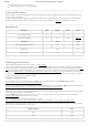
Header J1 Header J2 Jumper Blocks
Pin Signal Description Pin Signal Description Jumper State Description
1 IRQ Interrupt 1 IRQ Interrupt JP3 Enabled communication enabled on IRQ
line
2 SS Sample Start 2 SS Sample Start JP4 Enabled communication enabled on SS
line
3 SCL Serial Clock 3 SCL Serial Clock JP1 Enabled 2.2 kΩ resistors enabled on the
SCL line
4 SDA Serial Data 4 SDA Serial Data JP2 Enabled 2.2 kΩ resistors enabled on the
SDA line
5 GND
()
Power Supply
Ground
5 GND
()
Power Supply
Ground
6 VCC
()
Power Supply
(3.3V)
6 VCC
()
Power Supply
(3.3V)
The jumper settings when using the demos are JP1: Enabled, JP2: Enabled, JP3: Enabled, JP4: Enabled.
Any external power applied to the Pmod ToF must be within 2.7 V and 3.3 V to ensure that the on-board chips operate correctly;
however, it is recommended that Pmod is operated at 3.3 V. The Pmod ToF does not draw more than 225 mA of current.
Measurements
fmod
D
= ∗ Δ
φ
(1)
C
4 ∗
π
∗
fmod
fmod
Δ
φ
Pinout Table Diagram