
User Manual


21/02/2020 Pmod ToF Reference Manual [Reference.Digilentinc]
https://reference.digilentinc.com/reference/pmod/pmodtof/reference-manual?_ga=2.11378417.475818879.1582283268-1306234254.1582101049 5/9
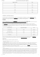
Register address Data
0x13 0x71
0x18 0x22
0x19 0x22
0x60 0x01
0x90 0x0F
0x91 0xFF
In order to perform an accurate distance measurement, the Pmod ToF needs to be calibrated. It contains an EEPROM () where the
calibration can be stored. At the factory, the EEPROM () was programmed with a default calibration profile that helps in performing
measurements in a range of 30cm-3m. To obtain the best accuracy, a calibration must be performed.
The Pmod is equipped with a non-volatile EEPROM () memory chip from Atmel: AT24C04D ( datasheet
(http://ww1.microchip.com/downloads/en/devicedoc/atmel-8896e-seeprom-at24c04d-datasheet.pdf) available on Microchip website) which has
4-Kbits of available space. The memory can be accessed over the I2C protocol at the address: 0x50h.
The EEPROM () stores two sets of calibration values. The factory calibration set contains the values for the generic calibration
performed when the device was manufactured, and cannot be altered. The user calibration set contains the values generated when the
user performs their own calibration. Initially the user calibration set is loaded with the factory calibration vales. It can always be restored
by copying the factory calibration set.
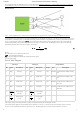
Section Content Section Base Address Size
Serial Number 0x00 16 bytes
User calibration data 0x10 16 bytes
Factory calibration data 0x20 16 bytes
Free Memory 464 bytes
Please consult the Pmod ToF Library User Guide for more information about usage of and communication with the EEPROM ()
module. For more details about the calibration process, read more in the Calibration Procedure section below.
There are three types of calibrations required for Pmod ToF:
1. Magnitude calibration: compensates for the emitter current.
2. Crosstalk calibration: compensates for electrical crosstalk observed by the photodiode. At close range a large return signal values for
crosstalk has a minor impact on distance measurements. At the far end of the distance range, the crosstalk might exceed the signal,
adding significant error to measurements. In order to perform this calibration, the receiver or both optics need to be covered with the
foam included in the package to make sure there is no return path for the IR signal emitted by the LED (). If the optics are not correctly
covered, it will result in large errors when measurements are taken.
NOTE: The foam included in the package might have some deformities due to the cutting process. In order to insure the best calibration please use the flat side of
the foam.
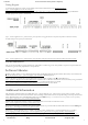
3. Distance calibration: compensates for variation in delay of the emitter, photodiode, and the ISL29501 that will change the signal path
delay. It will create a coefficient that will be subtracted in each measurement. For this calibration the user must set a predefined distance
for which the calibration is performed. A good calibration at 1.5m can result in the ability of the Pmod ToF to measure up to 5 meters
with an error of only a few centimeters. The calibrations should be performed at smaller distances (below 1.5m) to avoid distortion and
noise that can affect the calibration. In order to perform the distance calibration, a white target (a target with high IR reflective capacity)
should be placed at the desired distance from the Pmod ToF. The Pmod should be also placed at least 40cm above the ground or table
and no objects should be within the +/-3° area of the optics. The farther the measurement is taken from the ToF, the bigger the area
should be.
Calibration and Measurements
EEPROM
Calibrations