
User Manual


21/02/2020 Pmod ToF Reference Manual [Reference.Digilentinc]
https://reference.digilentinc.com/reference/pmod/pmodtof/reference-manual?_ga=2.11378417.475818879.1582283268-1306234254.1582101049 4/9
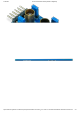
6-pin Pmod connector with I²C interface
Pass-through Pmod host port for daisy chaining
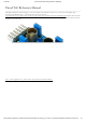
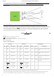
The Pmod ToF is designed to digitally report the distance measured by the Time of Flight based signal processing integrated circuit. It
has up to 16-bits of resolution.
It operates using the principle of Square Wave Modulated Indirect Time of Flight (SWM-ITOF) in the frequency domain and obtains
distance measurements from the phase shift. The sensing is done by an external emitter (LED ()) and detector (Photodiode)
Parameter Min Typical Max Units
Power Supply Voltage 2.7 3.3 V
Serial Clock Frequency 10 100 400 kHz ()
Parameter Value Units
Maximum Current Consumed 55 mA
Wavelength 860 nm
Emission angle +/-3°
The Pmod ToF communicates with the host board via the I²C protocol
(https://reference.digilentinc.com/pmod/communication_protocols/i2c). By first sending the 7-bit I²C address of 01010111 (0x57) and then a
read/write bit (high/low logic level, respectively), followed by the register address of interest at a maximum clock frequency of 400 kHz
(), users can read and write Pmod ToF registers, thus implementing configuration of, calibration of, and reading of measurements from,
the Pmod ToF. Header J2 (https://reference.digilentinc.com/reference/pmod/pmodtof/start#j2_pinout) on the Pmod ToF is a pass-through
for all of the signals present on the main Header J1 (https://reference.digilentinc.com/reference/pmod/pmodtof/start#j1_pinout) to allow for
the daisy chaining of multiple I²C compatible modules.
All the registers used in the measurement and/or calibration process are described in the ISL29501 ISL29501 datasheet
(https://www.renesas.com/eu/en/www/doc/datasheet/isl29501.pdf).
There is a set of registers used at every chip initialization. The Chip Initialization routine is described in ISL29501 Firmware Routines
(an1724.pdf) documentation (https://www.renesas.com/us/en/www/doc/application-note/an1724.pdf ?
_ga=2.225173722.1727551698.1569238908-634851053.1552119990).
These values (see table below) are set by Digilent and the user must be very careful changing them. In this situation the user must modify
these values before performing manual calibration.
Please read ISL29501 (https://www.renesas.com/in/en/www/doc/datasheet/isl29501.pdf ?_ga=2.219327705.1727551698.1569238908-
634851053.1552119990) documentation before proceeding.
For more information, consult the Pmod ToF Library user guide
(https://reference.digilentinc.com/reference/pmod/pmodtof/zynqlibraryuserguide#isl29501_-_time_of_flight_tof_integrated_circuit).
NOTE: Prior to restoring the factory calibration, if the user modified these register values, they must be restored to the values specified
below, otherwise the measurements won't be correct.
Register address Data
0x10 0x04
0x11 0x6E
Functional Description
Specifications
Interfacing with the Pmod
Application Register Map