
User Manual


At board power-up, Platform MCU detects if a SYZYGY peripheral board (“Pod”) is connected to Genesys ZU and signals this to the
FPGA. If a SYZYGY Pod was detected, the SYZYGY_DETECTEDN pin (H11) is driven LOW. Otherwise the pin is driven HIGH.
If VADJ_AUTO pin (G10) from FPGA is LOW, the Platform MCU establishes the correct VADJ voltage value based on
VADJ_LEVEL1 (AC13) and VADJ_LEVEL0 (AC14) input pins, regardless of whether a syzygy pod and/or FMC mezzanine module is
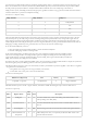
connected. Table 10.2.1.1 presents the VADJ level encoding.
Table 10.2.1.1: VADJ levels encoding
VADJ_LEVEL1 VADJ_LEVEL0 VADJ level
0 0 VADJ disabled
0 1 1.2V
1 0 1.5V
1 1 1.8V
Although neither FMC mezzanine modules nor SYZYGY pods are designed to be plug-and-play and their detection needs to be done
only at board power-up, the VADJ voltage value can still change during board operation. Due to this, VADJ_AUTO signal value can
change during board operation. The Platform MCU will detect the pin change and will adjust the VADJ voltage level according to the
actual VADJ_LEVEL1 and VADJ_LEVEL0 pins state. The voltage rail will reach its power good threshold in maximum 60 ms after the
falling edge of VADJ_AUTO. The power good threshold is set to 100 mV less than the nominal voltage.
To set the desired VADJ level you have to:
1. Drive the VADJ_LEVEL1 and VADJ_LEVEL0 to encode the desired VADJ level.
2. Generate a falling edge condition on VADJ_AUTO.
In the current implementation, the FPGA must detect the correct VADJ level required by SYZYGY and FMC modules
and must set the VADJ_LEVEL1 and VADJ_LEVEL0 signals accordingly. The VADJ_LEVEL1 and VADJ_LEVEL0
signals will be taken into account by the Platform MCU only if the VADJ_AUTO signal is driven LOW by the FPGA. If
VADJ_AUTO is HIGH, the VADJ power rail is disabled.
On Genesys ZU there is a
LED () labeled with PMCU. This is the status led that is used by the Platform MCU to display the system fault
that has the highest priority. The blinking pattern for each fault is presented in Table 10.2.1.2.
After Platform MCU startup, if no issues were encountered, this
LED () should blink in a pattern Long Blink – Short Pause - Long Blink
– Long Pause then it should turn off.
A “long blink” and a “long pause” last for approximately 1 second each;
A “short blink” and a “short pause” last for about 200ms each;
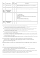
Table 10.2.1.2: Fault blink patterns
Blink Pattern (Repeated) Issue Priority Comments
Long Blink – Long Pause Fan Speed Fault 0 Register 0x04 Bit 0
The Platform MCU exposes to the PC a register interface, accessible via UART. The full register map is shown in Table 10.2.1.3.
Table 10.2.1.3: Register map
Offset Register Name
Size
[bits] R/W Description
0x00 ID Register 8 R It contains a fixed value, used for determining if the Platform MCU is alive
and responding over UART (0x00).
0x01 Firmware Version 8 R It contains the firmware major version on bits 7-4 and the minor version on
bits 3-0
0x02 Scratch Register 8 R/W Read/write register used to test both the write and the read register interfaces.
0x03 Measured FPGA Core
Temperature
8 R FPGA Temperature value, as computed by the Platform MCU based on the
thermal diode measurement.