
User Manual


The tri-color
LED () has three input signals that drive the cathodes of three smaller internal LEDs: one red, one blue, and one green.
Driving the input signal corresponding to one of these colors low will illuminate the internal LED (). The input signals are driven by the
Zynq PL through a transistor, which inverts the signals. Therefore, to light up the tri-color
LED (), the corresponding PL pins need to be
driven high. The tri-color LED () will emit a color dependent on the combination of internal LEDs that are currently being illuminated.
For example, if the red and blue signals are driven high and green is driven low, the tri-color
LED () will emit a purple color.
Note: Digilent strongly recommends the use of pulse-width modulation (PWM) when driving the tri-colo LEDs. Driving any of the signals to a steady logic '1'
will result in the
LED () being illuminated at an uncomfortably bright level. This can be avoided by ensuring that none of the tri-color signals are driven with
more than a 50% duty cycle. Using PWM also greatly expands the potential color palette of the tri-color LED (). Individually adjusting the duty cycle of each
color between 0% and 50% causes the different colors to be illuminated at different intensities, allowing virtually any color to be displayed.
The individual high-efficiency LEDs are anode-connected to the Zynq Ultrascale+ via 330-ohm resistors, so they will turn on when a
logic high voltage is applied to their corresponding I/O pin.
Tying all the features of the Genesys ZU together into a computing platform requires an embedded controller independent of the
MPSoC. We call it Platform MCU. Part of the platform is the coin battery, the fan, a temperature sensor inside the MPSoC and Power
Management Units (PMU). Management is done through dedicated signals or over the main I C bus.
Almost all I C-capable peripherals are accessible through the main I C bus. Multiple masters have access:
Platform MCU in the Auxiliary 3.3 V domain through MUX_SCL and MUX_SDA,
3-pin header J36 in the Auxiliary 3.3 V domain through MUX_SCL and MUX_SDA,
MPSoC PS-side in the Main 3.3 V domain through MUX_SCL_LS and MUX_SDA_LS in Bank 500,
MPSoC PL-size in the Main 3.3 V domain through MUX_SCL_LS and MUX_SDA_LS in Bank 46*/26.
It follows that any I C master controller implementation in the MPSoC must be multi-master tolerant and must support arbitration.
The Platform MCU is implemented by a Microchip ATmega328PB. It is on the auxiliary 3.3V power domain, immediately available after
power-up. This power domain is independent of the PMUs which provide main power, giving the Platform MCU control over main
power. It also shares the main I C bus with the MPSoC, giving it access to all the critical peripherals. Other features include MPSoC
temperature sensing, fan speed control, and VADJ voltage setting.
The Platform MCU program memory has two sections:
Application where the firmware resides
Bootloader where the bootloader resides.
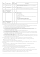
The Platform MCU has the following interfaces on Genesys ZU:
FPGA temperature sensing and fan control with feedback
PMU interfaces
SYZYGY connector interface
FMC connector interface
UART interface to the PC
The Platform MCU monitors the FPGA temperature and adjust the fan speed accordingly. Also, it checks that the actual fan speed is
close to the set value and reports a fault to the PC otherwise. FPGA temperature monitoring is performed using the temperature diode
inside the FPGA.
9.4. Green LEDs
10. Platform Management
2
10.1. Main I2C bus
2 2
2
2
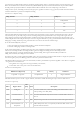
The only slave device that can be accessed after power-on is an 8-channel I C multiplexer, a TI TCA9548A, responding to address
1110000b. The rest of the slaves are distributed on the eight channels numbered from 0 to 7. To access a device on a particular channel,
address the multiplexer first and write a single byte to it with the bit corresponding to the desired channel set to 1. After the STOP
condition, the multiplexer will unite all the enabled channels and the main bus. Now a slave on the enabled channels can be accessed by
its respective address. Make sure that there are no address conflicts on enabled channels. For example, having a Pcam 5C connected to
each of the two MIPI/Pcam ports, and enabling both channel 0 and 1 simultaneously will cause a conflict. This might be desired,
allowing writing the same data to both Pcams, but reading is problematic and arbitration will happen. The recommended approach is
having just one of the channels enabled at any time.
10.2. Platform MCU
2
10.2.1. Application Section