
User Manual


The vivado-library and vivado-hierarchies repositories on the Digilent Github (https://github.com/Digilent/) contains pre-made IP
cores for many of these Pmods that greatly reduce the work of integrating them into your project. See the Pmod-related tutorials on the
Genesys ZU Resource Center for help using them.
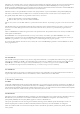
PMODS JA, JB, JC, JD
Dual Digital/Analog PMOD PMOD JB PMOD JC PMOD JD
JA1_P:W10 JB1:AE13 JC1:E13 JD1:E15
JA2_P:AA11 JB2:AG14 JC2:G13 JD2:A14
JA3_P:AB10 JB3:AH14 JC3:B13 JD3:B15
JA4_P:Y9 JB4:AG13 JC4:D14 JD4:F15
JA1_N:Y10 JB7:AE14 JC7:F13 JD7:E14
JA2_N:AA10 JB8:AF13 JC8:C13 JD8:B14
JA3_N:AB9 JB9:AE15 JC9:C14 JD9:D15
JA4_N:AA8 JB10:AH13 JC10:A13 JD10:A15
On the Genesys ZU, one of the Pmod connectors is not like the others. Designated by JA, the Pmod connector is wired to pins that can
serve as auxiliary inputs to the system monitor
ADC () inside the MPSoC. These pins are in a VADJ-powered bank, so the VCC () pins
are not powered from the 3.3 V rail, like on regular Pmods, but from VADJ. VADJ on the Genesys ZU is in the 1.2 V - 1.8 V range. Pins
1-7, 2-8, 3-9, 4-10 are paired and routed differentially. Although these pins can be used in digital mode, the particularities of this
connector must be taken into account when connecting Pmod modules to it.
The push-buttons are “momentary” switches that normally generate a low output when they are at rest, and a high output only when
they are pressed.
The slide switches generate constant high or low inputs depending on their position: when the slide is in a low position (i.e. close to the
lower board edge), the generated input is low; when the slide is in a high position (i.e. close to the center of the board), the generated
input is high.
Digilent produces a large collection of Pmod accessory boards that can attach to the Pmod ports to add ready-made functions like
A/D’s, D/A’s, motor drivers, sensors, and other functions.
8.5. Dual Digital/Analog Pmod
9. Basic I/O
The Genesys ZU includes five push-buttons, four slide switches, one tri-color LED
() and four green LEDs connected to the Zynq PL,
as shown in Figure 9.1 below. These I/Os are connected to the Zynq via series resistors to prevent damage from inadvertent short
circuits (a short circuit could occur if a pin assigned to a push-button was inadvertently defined as an output). The five push-buttons are
arranged in a plus-sign configuration (center, left, right, up and down buttons, respectively).
Genesys ZU also has two push-buttons and one green LED () connected to the Zynq PS: push-buttons BTN0 and BTN1 are connected
to MIO11 and MIO10, respectively, and the green LED () is connected to MIO21.
9.1. Push-Buttons
9.2. Slide Switches
9.3. Tri-Color LED