
User Manual


The Genesys ZU has four status LEDs:
1. ERR : it is asserted for accidental loss of power, a hardware error or an exception in the Platform Management Unit (PMU);
2. STS : it is asserted in secure lockdown state;
3. INIT : indicates the PL is initialized after the power-on reset (POR);
4. DONE : it is asserted when the PL configuration is completed;
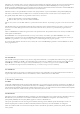
System 7 6 5 4 3 2 1 0 8
Slot 0 1 2 3 4 5 6 7 8
ECC byte (lane 8) is equivalent to any of the data bytes from the perspective of the DRAM components. The controller and SODIMM
connector have dedicated ECC pins (CBx), which are not used on non-ECC systems. Therefore the ECC lane (CBx) cannot be swapped
with other lanes. However, byte and bit swaps in data lanes are transparent to the ECC feature since any swap performed upon write is
reversed back upon read.
The Write CRC is a new feature of DDR4 and is complementary and unrelated to the ECC feature. Write CRC protects data in transit,
ECC protects data in storage. CRC is calculated both by the controller and the DRAM to avoid data corruption in the the write data
burst. It can detect single bit, double bit, odd count and one multi-bit UI vertical column errors. Upon error detection, DRAM will assert
the ALERT_n line. The controller should retry the write upon error.
It should be enabled in systems that expect a high amount of signal integrity issues and where high reliability is desired. It trades data rate
for reliability. CRC support is optional in SODIMM modules. Even if the module supports it, implementation is not easy. For CRC to
work the controller must know what pin swaps were performed on the memory interface. In case of SODIMM modules, there are some
restricted pin swaps possible and must be documented in the SPD
EEPROM (). The controller is expected to read these, combine it with
pin swaps on the system board and assign the bits to CRC inputs accordingly. According to AR# 68788
(https://www.xilinx.com/support/answers/68788.html) this can be achieved through the DDRC.DQMAP registers, not well documented.
The Genesys ZU features a serial flash memory from ISSI. This memory is used to provide non-volatile code and data storage. It can be
used to initialize the PS subsystem as well as configure the PL. The key device attributes are:
Part number: IS25LP256D-JMLE
Size: 256Mbit / 32Mbyte
1-bit, 2-bit and 4-bit bus widths supported
80MHz Normal Read, Up to 166MHz Fast Read
Up to 664Mb/s in quad-spi mode
Powered from 3.3V
2.5. Status LEDs
3.
Main Memory
Main memory is a single-slot populated DDR4 SODIMM, always upgradeable by the user. It is wired to the PS (Processing System) side
using the hard-core memory controller. The bundled module is a 4GiB Kingston HyperX HX424S14IB/4. Although the module
supports DDR4-2400 CL14-14-14 timing, data rate is limited by the MPSoC and the board. The 5EV board variant supports
DDR4-2133*, while the 3EG supports DDR4-1866.
Although the bundled module is not ECC-capable, the Genesys ZU is. Just pair it with an ECC module and enable the feature in the
Vivado MPSoC PS Configuration Wizard.
3.1. Implementation
There is a single SODIMM slot on the top side of the Genesys ZU just north of the MPSoC. It is wired to the PS-side memory
controller and supports any SODIMM module complying with the memory controller's restrictions.
The serial presence detect (SPD) interface is wired to MIO8 (DDR_SCL) and MIO9 (DDR_SDA), accessible through the I2C1
controller.
For better routing some byte swaps were performed detailed in Table 3.1.1. No nibble or bit swaps were needed.
Table 3.1.1: DDR4 interface byte swaps.
4. Storage
4.1. Quad-SPI Flash