
User Manual


VCC0V85_
INT () VCC12V0 0.825V / 0.85V / 0.875V 11A FPGA Internals
VTT0V6 VCC1V2_PSDDR 0.6V (0.49xVCC1V2_PSDDR-
0.02V… …
0.51xVCC1V2_PSDDR+0.02V)
1A DDR4 VTT
VREF0V6 VCC1V2_PSDDR 0.6V
(0.49xVCC1V2_PSDDR… …
0.51xVCC1V2_PSDDR)
0.01A DDR4 reference voltage
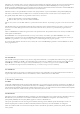
The board is powered up by sliding the SW5 switch to the ON position. The voltage supplies start-up sequence is defined by
implementing a power good daisy chain that selectively enables groups of voltages that should start together. All supplies use a soft start
mechanism to reduce the surge currents during turn on. The start-up sequence is suggested in Figure 1.2.1 and can be described in the
following steps:
1. When the ramping VCC12V0 exceeds the turn-ON threshold of IC78, the VCC5V0_STABLE rail starts up. This triggers the
VCC3V3_STABLE supply and powers the IC81 internal logic. The VCC3V3_STABLE rail powers the platform MCU. Its valid
state is marked by the green Aux power ON
LED () (LD19).
2. When the protection circuit detects a valid 12V input, it asserts the INPUT_PGD signal that triggers the VCC5V0 startup. This
voltage powers the internal logic of IC83 and IC84.
3. If VCC5V0 reaches its power-good threshold, the PGOOD0=En1 signal is asserted. This enables the VCC0V85_
INT (),
VCC0V9_MGTAVCC*, VCC2V7_LDOIN and VCC0V9_VCU* voltages. The power-good signals of all these supplies are joined
in a wired AND configuration and activate PGOOD1 when all rails have reached their nominal voltages.
4. When all voltages from the first starting group have crossed their power-good thresholds, the PGOOD1=En2 signal is asserted.
This enables the VCC1V8_AUX and VCC0V85_PSMGTRAVCC voltages of the second group.
5. A similar trigger mechanism applies to the third (PGOOD2=En3) and the fourth (PGOOD3=En4) voltage groups as illustrated in
Figure 1.2.1. The fourth group also includes the dedicated DDR4 power supply with all its output voltages.
6. If all voltages from the fourth group have succesfully reached their designed values, their power-good (PG_ALL) lights up the
green Main Power ON
LED () (LD20). At this point the board is fully functional.
Note: the VADJ rail is controlled separately by the platform MCU that must first set VADJ depending on the peripherals using those
voltage. VADJ is in the fourth start-up group but it is conditioned by a valid EN_VADJ_CTRL signal generated by the platform MCU.
Sliding the SW5 switch to the OFF position disables the power supplies by pulling INPUT_PGD to ground. The capacitor C405
connected to the EN terminal of the LM5060 monitoring IC delays the VCC12V0 turn off with approximately 200ms until all power
supplies have been safely powered off.
1. PS TAP (main PS controller with IDCODE)
2. PL TAP (used for PL configuration and boundary scan)
3. DAP (used for ARM debugging, Real time processing unit (RPU) and Application Processing Unit (APU))
Taking into account this architecture, when placed in JTAG boot mode, the processor (APU) will wait until software is loaded by a host
computer using the Xilinx tools. After software has been loaded, it is possible to either let the software begin executing, or step through it
line by line using Xilinx SDK.
It is also possible to directly configure the PL over JTAG, independent of the processor. This can be done using the Vivado Hardware
Server.
The Genesys ZU is configured to boot in Cascaded JTAG mode, which allows the PS to be accessed via the same JTAG port as the PL.
1.3. Power Sequencing
2.
MPSoC Boot Process
2.1. JTAG Boot Mode
JTAG is the most important component of the debug features for software and PL development. The JTAG architecture has three Test
Access Port (TAP) controllers: