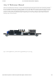
22.8.2018 Arty A7 Reference Manual [Reference.Digilentinc] Arty A7 Reference Manual The Arty A7, formerly known as the Arty, is a ready-to-use development platform designed around the Artix-7™ Field Programmable Gate Array (FPGA) from Xilinx. It was designed specifically for use as a MicroBlaze Soft Processing System. When used in this context, the Arty A7 becomes the most flexible processing platform you could hope to add to your collection, capable of adapting to whatever your project requires.
2.8.2018 Arty A7 Reference Manual [Reference.Digilentinc] https://reference.digilentinc.
22.8.2018 Arty A7 Reference Manual [Reference.Digilentinc] https://reference.digilentinc.
22.8.2018 Arty A7 Reference Manual [Reference.Digilentinc] https://reference.digilentinc.
22.8.2018 Arty A7 Reference Manual [Reference.Digilentinc] https://reference.digilentinc.
22.8.2018 Arty A7 Reference Manual [Reference.Digilentinc] https://reference.digilentinc.
22.8.2018 Arty A7 Reference Manual [Reference.Digilentinc] https://reference.digilentinc.
22.8.2018 Arty A7 Reference Manual [Reference.Digilentinc] https://reference.digilentinc.
22.8.2018 Arty A7 Reference Manual [Reference.Digilentinc] https://reference.digilentinc.
22.8.2018 Arty A7 Reference Manual [Reference.
22.8.2018 Arty A7 Reference Manual [Reference.Digilentinc] The Arty A7 is fully compatible with the high-performance Vivado ® Design Suite. It is supported under the free WebPACK™ license, so designs can be implemented at no additional cost. This free license includes the ability to create MicroBlaze™ soft-core processor designs. Design resources, example projects, and tutorials are available for download at the Arty Resource Center, accessible from reference.digilentinc.com. (https://reference.
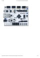
22.8.2018 Arty A7 Reference Manual [Reference.Digilentinc] Callout Description Callout Description Callout Description 6 Power good LED () 13 chipKIT processor reset jumper 20 Micron DDR3 memory 7 User LEDs 14 FPGA programming mode 21 Dialog Semiconductor DA9062 power supply 1 Purchasing Options The Arty A7 can be purchased with either a XC7A35 or XC7A100 FPGA loaded. These two Arty A7 product variants are referred to as the Arty A7-35 and Arty A7-100, respectively.
22.8.2018 Arty A7 Reference Manual [Reference.Digilentinc] What makes the Arty A7 so flexible is its FPGA. Among their many features, FPGAs have the ability to transform into a custom software-defined System-on-a-Chip (SoC). These “Soft SoC” FPGA configurations are designed graphically using a tool called Vivado IP Integrator (Vivado IPI). In this tool, pre-built peripheral blocks are dragged from an extensive library and dropped into your processing system as you see fit.
22.8.2018 Arty A7 Reference Manual [Reference.Digilentinc] (https://reference.digilentinc.com/_detail/reference/programmable-logic/arty-a7/arty-a7-rev-e-power.png?id=reference%3Aprogrammablelogic%3Aarty-a7%3Areference-manual) Figure 3.1 Arty A7 Power Circuit The USB port can deliver enough power for the vast majority of designs. However, a few demanding applications, including any that drive multiple peripheral boards, might require more power than the USB port can provide.
22.8.2018 Arty A7 Reference Manual [Reference.Digilentinc] Maximum Current Supply Circuits Device 0.95V (1.0V)2) FPGA Core and Block RAM () IC11: Dialog Semiconductor DA9062 2.5A 1.8V FPGA Auxiliary IC11: Dialog Semiconductor DA9062 1.5A 1.35V DDR3L and associated FPGA bank IC11: Dialog Semiconductor DA9062 2.5A 0.675V DDR3L IC17: Diodes Incorporated AP2303 1.75A 1.25V XADC Analog Reference IC14: Texas Instruments REF3012 25mA Table 3.1. Arty A7 Power Rails.
22.8.2018 Arty A7 Reference Manual [Reference.Digilentinc] 3.3 5V Supply Power Monitoring The Arty A7 includes circuitry for monitoring the voltage of the 5 Volt supply as well as the current consumed from this supply. A voltage divider is used to scale the 5V input voltage to be within the range (0-1V) that the on-chip 12-bit ADC () is capable of measuring. The 5V supply voltage is divided by 5.99 and then fed into Auxiliary Channel 1 on the XADC of the Artix-7 FPGA.
22.8.2018 Arty A7 Reference Manual [Reference.Digilentinc] After being successfully programmed, the FPGA will cause the “DONE” LED () to illuminate. Pressing the “PROG” button at any time will reset the configuration memory in the FPGA. After being reset, the FPGA will immediately attempt to reprogram itself from whatever method has been selected by the programming mode jumpers. The following sections provide greater detail about programming the Arty A7 using the different methods available. 4.
22.8.2018 Arty A7 Reference Manual [Reference.Digilentinc] Data mask Enabled Recommended Input Clock Period 6000 ps (166.667 MHz ()) Output Driver Impedance Control RZQ/6 Controller Chip Select pin Enabled Rtt (nominal) – On-die termination RZQ/6 Internal Vref Enabled Internal termination impedance 50ohms The MIG Wizard will require the fixed pin-out of the memory signals to be entered and validated before generating the IP core.
22.8.2018 Arty A7 Reference Manual [Reference.Digilentinc] Vivado IPI based designs can access the PHY using either the AXI EthernetLite IP core, the AXI 1G/2.5G Ethernet Subsystem IP core, or the Tri Mode Ethernet MAC IP core. A 25 MHz () clock needs to be generated for the X1 pin of the external PHY, labeled ETH_REF_CLK in the Arty A7 schematic.
22.8.2018 Arty A7 Reference Manual [Reference.Digilentinc] The CK_RST signal (see the Arty A7 Schematic) is also connected to the FT2232HQ device via JP2. When JP2 is shorted, the FT2232HQ can trigger a Microblaze reset, mimicking the behavior of Arduino and chipKIT boards when sketches are loaded. Note the CK_RST signal is also connected to the red RESET button and the RST pin of J7 on the shield connector (these connections are not shown in the figure below).
22.8.2018 Arty A7 Reference Manual [Reference.Digilentinc] corresponding signals need to be driven high. The tri-color LED () will emit a color dependent on the combination of internal LEDs that are currently being illuminated. For example, if the red and blue signals are driven high and green is driven low, the tri-color LED () will emit a purple color. Note: Digilent strongly recommends the use of pulse-width modulation (PWM) when driving the tri-color LEDs.
.8.2018 Arty A7 Reference Manual [Reference.Digilentinc] switching speeds. The signals are paired to the adjacent signals in the same row: pins 1 and 2, pins 3 and 4, pins 7 and 8, and pins 9 and 10. Traces are routed 100 ohm (+/- 10%) differential. These connectors should be used only when high speed differential signaling is required or the other Pmods are all occupied. If used as single-ended, coupled pairs may have significant crosstalk.
22.8.2018 Arty A7 Reference Manual [Reference.
22.8.2018 Arty A7 Reference Manual [Reference.Digilentinc] For more information on the electrical characteristics of the pins connected to the FPGA, please see the Artix-7 datasheet (http://www.xilinx.com/support/documentation/data_sheets/ds181_Artix_7_Data_Sheet.pdf) from Xilinx. 11.2 Shield Analog I/O The pins labeled A0-A11 and V_P/V_N are used as analog inputs to the XADC module of the FPGA. The FPGA expects that the inputs range from 0-1 V.
22.8.2018 Arty A7 Reference Manual [Reference.Digilentinc] First Name Last Name Email Address Submit Our Partners Xilinx University Program Help Customer Info Technical Support Forum Videos Company Info About Us (https://youtube.com/user/digilentinc) (https://store.digilentinc.com/ (https://store.digilentinc.com/partners/xilinx(https://forum.digilentinc.com) FAQ pageid=26) university-program/) Reference Wiki (https://resource.digilentinc.com/verify/faq) Shipping & Returns (https://reference.
22.8.2018 Arty A7 Reference Manual [Reference.Digilentinc] (https://www.reddit.com/r/digilent) (https://www.linkedin.com/company/1454013) (https://www.flickr.com/photos/127815101@N07) https://reference.digilentinc.


