300 Henley Court Pullman, WA 99163 509.334.6306 www.digilentinc.com ChipKIT MX3 Board Reference Manual Revised November 7, 2013 This manual applies to the ChipKIT MX3 REV ? Table of Contents Table of Contents .................................................................................................................. 1 Overview............................................................................................................................... 3 Specifications ..............................
ChipKIT MX3 Board Reference Manual 9 Analog Inputs............................................................................................................... 14 10 A/D Converter Reference ............................................................................................. 15 11 Timers ......................................................................................................................... 15 12 Output Compare ...................................................................
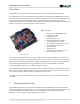
ChipKIT MX3 Board Reference Manual Overview ChipKIT MX3 is the new name for Cerebot MX3. This board retains all functionality of the Cerebot MX3. The ChipKIT MX3 is a microcontroller development board based on the Microchip PIC32MX320F128H, a member of the 32-bit PIC32 microcontroller family. It is compatible with Digilent’s line of Pmod™ peripheral modules, and is ® suitable for use with the Microchip MPLAB IDE tools.
ChipKIT MX3 Board Reference Manual The ChipKIT MX3 is immediately useable with the MPIDE. Additional hardware is required to use the Microchip MPLAB tools. 1.1 Using the ChipKIT MX3 with the MPIDE ChipKIT and the MPIDE is a PIC32 based hardware and software system compatible with many existing Arduino™ code examples, reference materials, and other resources. The MPIDE development platform was produced by modifying the Arduino™ IDE and is fully backward compatible with the Arduino IDE.
ChipKIT MX3 Board Reference Manual Two red LEDs (LD1 and LD2) will blink when data is being sent or received between the ChipKIT MX3 and the PC over the serial connection. The header connector J3 provides access to the other serial handshaking signals provided by the FT232R. Connector J3 is not loaded at the factory but can be installed by the user to access these signals. 1.
ChipKIT MX3 Board Reference Manual • Use the “Configure.Select Device …” menu to select the PIC32MX320F128H • Use the “Programmer.Select Programmer” menu to select the “PICkit3” or other hardware programming tool being used. • Use the “File Import…” dialog box to navigate to and select the boot loader programming downloaded from the Digilent web site. The file name will be something like: chipKIT_Bootloader_MX3.hex • Use the “Programmer.Program” command to program all memories on the device. 1.
ChipKIT MX3 Board Reference Manual The 5V power bus, VCC5V0 can be powered from one of three sources: 1) The USB5V0 bus when the board is operating under USB power; 2) The output of the on-board 5V regulator when operating from an external 7V–15V supply; or 3) Directly from the external supply when operating from a regulated 5V external supply and jumper JP2 is in the BYP position. Switchover from USB power to external power is done automatically and the external supply will be used if both are present.
ChipKIT MX3 Board Reference Manual Digilent Pmods are a line of small peripheral modules that provide various kinds of I/O interfaces. The Pmod product line includes such things as button, switch and LED modules, connector modules, LCD displays, high current output drivers, and many others. There are two styles of Pmod connector: six-pin and twelve-pin. Both connectors use standard pin headers with 100mil spaced pins.
ChipKIT MX3 Board Reference Manual 4 Digital Inputs and Outputs The ChipKIT MX3 board provides access to 40 of the I/O pins from the PIC32 microcontroller via the Pmod 2 2 connectors. Two additional I/O pins can be accessed via the I C connector, J2. Any of the pins on the Pmod or I C 2 connectors can be individually accessed for digital input or output. Note that when the I C signals on J2 are being 2 used for I C communications, they are not available for general purpose I/O.
ChipKIT MX3 Board Reference Manual 4.1 User LEDs Two LEDs are provided, LD4 and LD5, connected to I/O port F bits 0 and 1 (RF00 and RF01). LATF Bit 0 is connected to LD4 and bit 1 is connected to LD5. The LEDs are turned on or off by configuring these two pins as outputs and driving them high or low. Driving the pin high turns the LED on, driving it low turns it off. These I/O pins are dedicated to use with the LEDs and are not available at any connector.
ChipKIT MX3 Board Reference Manual the configuration settings specified using the #pragma config statement. Use #pragma config POSCMOD=XT to select the XT option. Using the internal system clock phase-locked loop (PLL), it is possible to select numerous multiples or divisions of the 8Mhz oscillator to produce CPU operating frequencies up to 80Mhz. The clock circuit PLL provides an input divider, multiplier, and output divider.
ChipKIT MX3 Board Reference Manual UART1 can be accessed from Pmod connector JB and UART2 can be accessed from Pmod connector JC using the following pins: • • • • U1CTS U1TX U1RX U1RTS JB-01 JB-02 JB-03 JB-04 • • • • U2CTS U2TX U2RX U2RTS JC-01 JC-02 JC-03 JC-04 Some of the pins on UART1 and SPI1 are shared on the PIC32 microcontroller. This means that UART1 and SPI1 can’t both be used at the same time.
ChipKIT MX3 Board Reference Manual • SDO1 • SDI1 • SCK1 • • • • SS2 JE-01 MOSI MISO SCK2 JB-02 JB-03 JB-04 JE-02 JE-03 JE-04 SPI1 is only laid out to support use as an SPI master. To use SPI1 as a slave device, it is necessary to use external wiring to connect the signals appropriately. When using SPI1 as a slave device, the SS1 signal is obtained from Pmod connector JD, pin 1 (JD-01). SPI2 is laid out on the board for use either as an SPI master or as an SPI slave device.
ChipKIT MX3 Board Reference Manual disabled via jumper blocks JP1 and JP10, near Pmod connector JA. The pull-ups are enabled by installing shorting blocks and are disabled by removing the shorting blocks. Generally, only one device on the bus will have the pullups enabled. There are no pull-up resistors provided on the ChipKIT MX3 for I2C2. If I2C2 is to be used, external pull-up resistors 2 must be provided. The operating voltage for the I C busses on the ChipKIT MX3 is 3.3V.
ChipKIT MX3 Board Reference Manual • • • • • • • A4 – JD-01, digital pin 24, RB2 A5 – JD-04, digital pin 27, RB9 A6 – JD-07, digital pin 28, RB12 A7 – JD-10, digital pin 31, RB13 A8 – JE-08, digital pin 37, RB5 A9 – JE-09, digital pin 38, RB4 A10 – JE-10, digital pin 39, RB3 10 A/D Converter Reference The PIC32 microcontroller provides two reference inputs to the analog to digital converter. Vref- is used set the lower reference level and Vref+ is used to set the upper reference level.
ChipKIT MX3 Board Reference Manual For detailed information on the operation of the PIC32 timers, refer to the PIC32 Family Reference Manual, Section 14, Timers. Control and operation of the timers is not explicitly provided in the current version of the MPIDE software. This capability will be added in a future version of the software. Timers are used implicitly by various core functions and libraries, however.
ChipKIT MX3 Board Reference Manual For detailed information on the operation and use of the input capture units, refer to the PIC32 Family Reference Manual, Section 15, Input Capture.
ChipKIT MX3 Board Reference Manual Appendix A: Connector Description and Jumper Settings Label Description JA–JE Pmod I/O Connectors These are used to access the I/O pins on the PIC32 microcontroller. JPA–JPE J1 J2 J3 J4 JP1 JP2 JP3 JP6, JP8 JP10, JP11 Pmod Connector Power Select Jumpers These are used to select the power supply voltage applied to the Pmod connector.
ChipKIT MX3 Board Reference Manual Appendix B: Example of Configuration Values The following example illustrates setting the configuration values in the PIC32 microcontroller on the ChipKIT MX3. The microcontroller configuration should be done in a single source file in the project, and is typically done in the ‘main’ project source file. This example sets all configuration values to valid values for the ChipKIT MX3 board.
ChipKIT MX3 Board Reference Manual Appendix C: Connector Pinout Tables Arranged by Microcontroller Pin Number PIC32 Pin # Connector Pin # Digital Pin # MCU Port Bit PIC32 Signal Name Notes 1 JA-08 5 RE05 PMD5/RE5 2 JA-09 6 RE06 PMD6/RE6 3 JA-10 7 RE07 PMD7/RE7 4 JE-04 35 RG06 SCK2/PMA5/CN8/RG6 5 JE-03 34 RG07 SDI2/PMA5/CN9/RG7 JP6 in M position 6 JE-02 33 RG08 SDO2/PMA3/CN10/RG8 JP8 in M position 7 N/A N/A 8 JE-01 32 9 N/A N/A VSS 10 N/A N/A VDD 11 JE-08
ChipKIT MX3 Board Reference Manual 34 JB-03 10 RF02 U1RX/SDI1/RF2 35 JB-04 11 RF06 U1RTS/BCLK1/SCK1/INT0/RF6 36 J2-3,J2-4 40 RG03 SDA1/RG3 37 J2-1,J2-2 41 RG02 SCL1/RG2 38 N/A N/A 39 N/A N/A RC12 OSC1/CLKI/RC12 40 N/A N/A RC15 OSC2/CLKO/RC15 41 N/A N/A 42 JE-07 36 RD08 IC1/RTCC/INT1/RD8 43 JB-01 8 RD09 IC2/U1CTS/INT2/RD9 44 JD-03 26 RD10 IC3/PMCS2/PMA15/INT3/RD10 45 JD-09 30 RD11 IC4/PMCS1/PMA14/INT4/RD11 46 JC-09 22 RD00 OC1/RD0 PIN_OC1 47 N/A
ChipKIT MX3 Board Reference Manual Arranged by Connector Pin Number and Digital Pin Number PIC32 Pin # Connector Pin # Digital Pin # MCU Port Bit PIC32 Signal Name Notes 60 JA-01 0 RE00 PMD0/RE0 61 JA-02 1 RE01 PMD1/RE1 62 JA-03 2 RE02 PMD2/RE2 63 JA-04 3 RE03 PMD3/RE3 64 JA-07 4 RE04 PMD4/RE4 1 JA-08 5 RE05 PMD5/RE5 2 JA-09 6 RE06 PMD6/RE6 3 JA-10 7 RE07 PMD7/RE7 43 JB-01 8 RD09 IC2/U1CTS/INT2/RD9 33 JB-02 9 RF03 U1TX/SDO1/RF3 34 JB-03 10 RF02 U1
ChipKIT MX3 Board Reference Manual 4 JE-04 35 RG06 SCK2/PMA5/CN8/RG6 42 JE-07 36 RD08 IC1/RTCC/INT1/RD8 11 JE-08 37 RB05 C1IN+/AN5/CN7/RB5 A8 12 JE-09 38 RB04 C1IN-/AN4/CN6/RB4 A9 13 JE-10 39 RB03 C2IN+/AN3/CN5/RB3 A10 36 J2-3,J2-4 40 RG03 SDA1/RG3 37 J2-1,J2-2 41 RG02 SCL1/RG2 58 N/A 42 RF00 RF0 PIN_LED1, (LD4) 59 N/A 43 RF01 RF1 PIN_LED2, (LD5) 7 N/A N/A MCLR 9 N/A N/A VSS 10 N/A N/A VDD 17 N/A N/A RB06 PGEC2/AN8/OCFA/RB6 18 N/A N/A RB0
ChipKIT MX3 Board Reference Manual Arranged by MCU Port and Bit PIC32 Pin # Connector Pin # Digital Pin # MCU Port Bit PIC32 Signal Name Notes 16 JC-07 20 RB00 PGED1/PMA6/AN0/VREF+/CVREF+/CN2/RB0 A2 15 JC-08 21 RB01 PGC1/AN1/VREF-/CVREF-/CN3/RB1 A3 14 JD-01 24 RB02 C2IN-/AN2/SS1/CN4/RB2 A4 13 JE-10 39 RB03 C2IN+/AN3/CN5/RB3 A10 12 JE-09 38 RB04 C1IN-/AN4/CN6/RB4 A9 11 JE-08 37 RB05 C1IN+/AN5/CN7/RB5 A8 17 N/A N/A RB06 PGEC2/AN8/OCFA/RB6 18 N/A N/A RB07 PGE
ChipKIT MX3 Board Reference Manual 62 JA-03 2 RE02 PMD2/RE2 63 JA-04 3 RE03 PMD3/RE3 64 JA-07 4 RE04 PMD4/RE4 1 JA-08 5 RE05 PMD5/RE5 2 JA-09 6 RE06 PMD6/RE6 3 JA-10 7 RE07 PMD7/RE7 58 N/A 42 RF00 RF0 PIN_LED1, (LD4) 59 N/A 43 RF01 RF1 PIN_LED2, (LD5) 34 JB-03 10 RF02 U1RX/SDI1/RF2 33 JB-02 9 RF03 U1TX/SDO1/RF3 31 JC-03 18 RF04 PMA9/U2RX/SDA2/CN17/RF4 32 JC-02 17 RF05 PMA8/U2TX/SCL2/CN18/RF5 35 JB-04 11 RF06 U1RTS/BCLK1/SCK1/INT0/RF6 37 J2-