300 Henley Court Pullman, WA 99163 509.334.6306 www.digilentinc.com ChipKIT™ PRO MX4 Board Reference Manual Revised November 7, 2013 This manual applies to Rev C of the board Table of Contents Table of Contents .................................................................................................................. 1 Overview............................................................................................................................... 3 1 Functional Description .................
ChipKIT Pro MX4 Reference Manual 10 Serial Peripheral Interface (SPI) ....................................................................................... 17 11 I2C ™ Interface ................................................................................................................ 18 11.1 Jumper Setting for I2C Pull Up Resistors ........................................................................... 19 11.2 On-Board I2C Peripheral Devices .....................................................
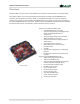
ChipKIT Pro MX4 Reference Manual Overview ChipKIT Pro MX4 is the new name for Cerebot MX4ck. This board retains all functionality of the Cerebot MX4ck. The ChipKIT Pro MX4 is a microcontroller development board based on the Microchip PIC32MX460F512L, a member of the 32-bit PIC32 microcontroller family. It is compatible with Digilent’s line of Pmod™ peripheral ® modules, and is suitable for use with the Microchip MPLAB IDE tools.
ChipKIT Pro MX4 Reference Manual ChipKIT Pro MX4 Circuit Diagram The ChipKIT Pro MX4 is designed to be easy to use and suitable for use by anyone from beginners to advanced users for experimenting with electronics and embedded control systems. A built in programming/debugging circuit ® compatible with the Microchip MPLAB IDE is provided on the board, so no additional hardware is required for use with MPLAB.
ChipKIT Pro MX4 Reference Manual running on the PIC32MX460 microcontroller is supported using an on-board programming/debugging circuit licensed from Microchip. The ChipKIT Pro MX4 is immediately useable with either the MPLAB IDE or the MPIDE. No additional hardware is required to use the board with the Microchip MPLAB tools. 2.
ChipKIT Pro MX4 Reference Manual file for the boot loader that was programmed into the board by Digilent at the factory is available for download from the ChipKIT Pro MX4 product page on the Digilent web site. Additionally, the boot loader source code is available in the chipKIT project repository at www.github.com/chipKIT32/pic32-Arduino-Bootloader. To reprogram the boot loader using MPLAB, perform the following steps: • Use the “Configure.
ChipKIT Pro MX4 Reference Manual 2.3 Additional Tools Information For additional information about the ChipKIT Pro MX4 board and the use and operation of the PIC32MX460F512L microcontroller, refer to the following documents in addition to this reference manual. The ChipKIT Pro MX4 Schematic, available on the ChipKIT Pro MX4 product page on the Digilent web site: www.digilentinc.com The PIC32MX3XX/4XX Family Data Sheet and the PIC32MX Family Reference Manual available from the Microchip web site: www.
ChipKIT Pro MX4 Reference Manual If the licensed debugger is connected to an active USB port, it enumerates with the host computer and once it has been successfully enumerated, it turns on the main board power supply by driving the PWR_ON signal high. If the licensed debugger is not connected to an active USB port, the PWR_ON signal is ignored and board power is turned on immediately by the power switch via transistor Q4.
ChipKIT Pro MX4 Reference Manual 3.1 Power Supply Monitor Circuit The ChipKIT Pro MX4 microcontroller can measure the power supply voltage on the BRD_VU and VS power busses using the provided power supply monitor circuits. This feature is especially useful when using batteries because it allows the microcontroller firmware to determine the charge state of the battery and potentially notify the user when a battery supply is low.
ChipKIT Pro MX4 Reference Manual Although ESD protection is provided between the connector pins and the microcontroller pins, ESD safe handling procedures should be followed when handling the circuit board. The pins on the microcontroller and other circuits on the board are exposed and can be damaged through ESD when handling the board. Digilent Pmod peripheral modules can either be plugged directly into the connectors on the ChipKIT Pro MX4 or attached via cables.
ChipKIT Pro MX4 Reference Manual On the ChipKIT Pro MX4, pin numbers 0–71 are used to access the pins on the Pmod connectors and pin numbers 2 72 and 73 are used for the two signal pins on the I C connector, J6. The pin numbers are assigned so that connector JA pin 1 (JA-01) is digital pin 0, JA pin 2 (JA-02) is digital pin 1, and so on. Pins 0-7 are on connector JA, pins 8-15 on JB, pins 16-23 on JC, pins 24-31 and so on.
ChipKIT Pro MX4 Reference Manual • • • • • • BTN1 – PIN_BTN1, pin 42, RA6 BTN2 – PIN_BTN2, pin 43, RA7 LD1 – PIN_LED1, pin 64, RB10 LD2 – PIN_LED2, pin 65, RB11 LD3 – PIN_LED3, pin 66, RB12 LD4 – PIN_LED4, pin 67, RB13 5.3 RC Servo Connectors The ChipKIT Pro MX4 provides eight 3-pin RC hobby servo connectors, labeled S1-S8, for direct control of servos in robotics and other embedded hardware actuator applications. The connectors share the I/O pins with Pmod connector JC.
ChipKIT Pro MX4 Reference Manual are rated for a maximum of 2A of current. USB power (J12 in the USB, DBG, or URT positions) should only be used to power a couple of servos to avoid exceeding the 500mA that a USB device is allowed to use. For the second case above: Remove the shorting block from jumper JP2 to make the VS servo power bus independent from the BRD_VU bus. Attach the servo power supply to screw terminal connector J5.
ChipKIT Pro MX4 Reference Manual 7 CPU Clock Source The PIC32 microcontroller supports numerous clock source options for the main processor operating clock. The ChipKIT Pro MX4 circuit board is designed to support either a silicon resonator from Discera, IC8, for use with the EC oscillator option, or an external crystal for use with the XT oscillator option. Standard production boards will have an 8Mhz Discera silicon resonator loaded and the EC oscillator option should be used.
ChipKIT Pro MX4 Reference Manual 8 USB Interface The PIC32MX460 microcontroller contains a USB 2.0 Compliant, Full Speed Device and On-The-Go (OTG) controller. This controller provides the following features: • • • • • USB full speed host and device support Low speed host support USB OTG support Endpoint buffering anywhere in system RAM Integrated DMA to access system RAM and Flash memory.
ChipKIT Pro MX4 Reference Manual Jumper JP6 is used to route power to the host connector being used. Place the shorting block in the “HOST” position when using the standard USB type A (host) connector, J17. Place the shorting block in the “OTG” position for use with the USB micro-AB (OTG) connector, J15. When operating as a USB host, the PIC32MX460 microcontroller controls application of power to the connected device via the VBUSON control pin.
ChipKIT Pro MX4 Reference Manual • • • • U1CTS U1TX U1RX U1RTS JE-01 JE-02 JE-03 JE-04 • • • • U2CTS U2TX U2RX U2RTS JH-01 JH-02 JH-03 JH-04 Detailed information about the operation of the UART peripherals can be found in the PIC32 Family Reference Manual, Section 21, UART. The USB Serial converter is connected to UART1. The MPIDE uses this to communicate with the boot loader.
ChipKIT Pro MX4 Reference Manual • SCK2 JB-04 • SS1 J1-01 (also JD-03) • SDO1 J1-02 (also JH-08) • SDI1 J1-03 (also JK-10) • SCK1 J1-04 (also JD-09) Detailed information about the operation of the SPI peripherals can be found in the PIC32 Family Reference Manual, Section 23, Serial Peripheral Interface. When using the ChipKIT Pro MX4 with the MPIDE and the chipKIT system, the SPI ports are accessed using either the standard chipKIT SPI library or using the Digilent DSPI library.
ChipKIT Pro MX4 Reference Manual Pull-ups Enabled Pull-ups Disabled 11.1 Jumper Setting for I2C Pull Up Resistors 2 When using the ChipKIT Pro MX4 with the MPIDE and the chipKIT system, the I C interfaces are accessed using the standard chipKIT Wire library, or the Digilent DTWI library. 2 The Wire library supports a single I C interface, I2C1 on J2. This is accessed using the Wire object. 2 The DTWI library supports both I C interfaces.
ChipKIT Pro MX4 Reference Manual 11.2 On-Board I2C Peripheral Devices 2 The ChipKIT Pro MX4 provides two on-board I C peripheral devices, a Microchip 24LC256 serial EEPROM, and a Microchip MCP4725 Digital to Analog Converter. These devices are both connected to I2C2. The 24LC256 is a 256Kbit (32Kbyte) serial EEPROM device to provide non-volatile memory storage. The MCP4725 is a single channel, 12-bit, serial digital to analog converter that provides an analog output voltage for various uses.
ChipKIT Pro MX4 Reference Manual 13 A/D Converter Voltage Reference The PIC32 microcontroller provides two voltage reference inputs to the analog to digital converter. Vref- is used to set the lower reference level and Vref+ is used to set the upper reference level. These reference inputs can be connected to internal references or to external references using two of the analog input pins. When the internal references are being used, Vref- is connected to VSS and Vref+ is connected to VDD.
ChipKIT Pro MX4 Reference Manual • TCK4 – JE-10, digital pin 39, RC03 • TCK5 – JK-10, digital pin 71, RC04 For detailed information on the operation of the PIC32 timers, refer to the PIC32 Family Reference Manual, Section 14, Timers. When using the MPIDE software, the symbols PIN_TCK2, PIN_TCK3, PIN_TCK4, and PIN_TCK5 can be used to access the timer input pins. Control and operation of the timers is not explicitly provided in the current version of the MPIDE software.
ChipKIT Pro MX4 Reference Manual The PIC32 microcontroller provides five input capture units. An input capture unit works in conjunction with a timer and monitors the state of an associated pin. When the pin changes state, the current value of the timer is captured. The input capture units can be used with either Timer2 or Timer3. The input capture unit can be programmed to be sensitive to either a rising edge, a falling edge, or both edges on the input pin.
ChipKIT Pro MX4 Reference Manual solder in a 32Khz watch crystal. The Citizen CFS206-32.768KDZF-UB is a crystal part that can be used in this location. Copyright Digilent, Inc. All rights reserved. Other product and company names mentioned may be trademarks of their respective owners.
ChipKIT Pro MX4 Reference Manual Appendix A: Connector Descriptions and Jumper Settings Label J1 J2 J3 & J4 J5 J6 J7 J8 J9 J10 J11 J12 J13 J14 J15 J16 Function SPI port #1 connector Because of multiple uses for the pins, the signals for SPI port #1 are scattered across multiple Pmod connectors. This connector provides all of the SPI port #1 signals on a single connector. All of the signal pins on this connector are shared with pins on various Pmod connectors.
ChipKIT Pro MX4 Reference Manual J17 J18 J19 JP1 JP2 JP3 JP4 JP5 JP6 Pin 20 on the PIC32MX460 microcontroller has multiple functions. It functions as the VBUSON control pin when acting as a USB host. It can be used as an analog input for the A/D converter or one of the analog comparators. It can also be used as a pin change interrupt input or as a general digital i/o.
ChipKIT Pro MX4 Reference Manual JP7 JP8 JP9 JP10 S1-S8 JPA – JPF & JPH-JPK Do not use Used for manufacturing test purposes. USB Serial converter reset disconnect This is used to connect/disconnect the USB serial converter reset circuit from the PIC32 MCLR pin. The shorting block must be in place on this jumper when using the chipKIT MPIDE development tools. Remove the shorting block if the USB serial converter is interfering with proper operation of the licensed debugger circuit.
ChipKIT Pro MX4 Reference Manual Appendix B: Example of Configuration Values The following example illustrates setting the configuration values in the PIC32 microcontroller on the ChipKIT Pro MX4. The microcontroller configuration should be done in a single source file in the project, and is typically done in the ‘main’ project source file. This example sets all configuration values to valid values for the ChipKIT Pro MX4 board.
ChipKIT Pro MX4 Reference Manual Appendix C: Connector Pinout Tables Arranged by Microcontroller Pin Number PIC 32 Pin # 1 Connector Pin # JC-04 ChipKIT Pin # 19 MCU Port Bit RG15 3 JA-08 5 RE05 PMD5/RE5 4 JA-09 6 RE06 PMD6/RE6 5 JA-10 7 RE07 PMD7/RE7 6 JD-04 27 RC01 T2CK/RC1 7 JD-10 31 RC02 T3CK/RC2 8 JE-10 39 RC03 T4CK/RC3 9 JK-10 71 RC04 SDI1/T5CK/RC4 10 JB-04 11 RG06 PMA5/SCK2/CN8/RG6 11 JB-03 10 RG07 PMA4/SDI2/CN9/RG7 12 JB-02 9 RG08 PMA3/SDO2/CN10/
ChipKIT Pro MX4 Reference Manual 41 JK-03 66 RB12 PMA11/AN12/RB12 also LD3 42 JK-04 67 RB13 PMA10/AN13/RB13 also LD4 43 JB-10 15 RB14 PMALH/PMA1/AN14/RB14 44 JB-07 12 RB15 PMALL/PMA0/AN15/OCFB/CN12/RB15 47 JE-01 32 RD14 CN20/U1CTS/RD14 48 JE-04 35 RD15 U1RTS/BCLK1/CN21/RD15 49 JH-03 50 RF04 PMA9/U2RX/CN17/RF4 50 JH-02 49 RF05 PMA8/U2TX/CN18/RF5 51 N/A N/A RF03 USBID/RF3 52 JE-03 34 RF02 U1RX/RF2 53 JE-02 33 RF08 U1TX/RF8 56 N/A N/A RG03 D-/RG3 US
ChipKIT Pro MX4 Reference Manual 87 JC-09 22 RF00 PMD11/RF0 also servo S7 88 JC-10 23 RF01 PMD10/RF1 also servo S8 89 JC-08 21 RG01 PMD9/RG1 also servo S6 90 JC-07 20 RG00 PMD8/RG0 also servo S5 91 JF-03 42 RA06 TRCLK/RA6 also BTN1 92 JF-04 43 RA07 TRD3/RA7 also BTN2 93 JA-01 0 RE00 PMD0/RE0 94 JA-02 1 RE01 PMD1/RE1 95 JC-03 18 RG14 TRD2/RG14 also servo S3 96 JC-01 16 RG12 TRD1/RG12 also servo S1 97 JC-02 17 RG13 TRD0/RG13 also servo S2 98 JA-
ChipKIT Pro MX4 Reference Manual Arranged by Connector Pin Number and Digital Pin Number PIC 32 Pin # 93 Connector Pin # JA-01 ChipKIT Pin # 0 MCU Port Bit RE00 94 JA-02 1 RE01 PMD1/RE1 98 JA-03 2 RE02 PMD2/RE2 99 JA-04 3 RE03 PMD3/RE3 100 JA-07 4 RE04 PMD4/RE4 3 JA-08 5 RE05 PMD5/RE5 4 JA-09 6 RE06 PMD6/RE6 5 JA-10 7 RE07 PMD7/RE7 14 JB-01 8 RG09 PMA2/SS2/CN11/RG9 12 JB-02 9 RG08 PMA3/SDO2/CN10/RG8 11 JB-03 10 RG07 PMA4/SDI2/CN9/RG7 10 JB-04 11 RG06
ChipKIT Pro MX4 Reference Manual 52 JE-03 34 RF02 U1RX/RF2 48 JE-04 35 RD15 U1RTS/BCLK1/CN21/RD15 19 JE-07 36 RE09 INT2/RE9 78 JE-08 37 RD03 OC4/RD3 71 JE-09 38 RD11 IC4/PMCS1/PMA14/RD11 8 JE-10 39 RC03 T4CK/RC3 66 JF-01 40 RA14 SCL1/INT3/RA14 also J2-01,J2-02 I2C1 67 JF-02 41 RA15 SDA1/INT4/RA15 also J2-03,J2-04 I2C1 91 JF-03 42 RA06 TRCLK/RA6 also BTN1 92 JF-04 43 RA07 TRD3/RA7 also BTN2 17 JF-07 44 RA00 TMS/RA0 38 JF-08 45 RA01 TCK/RA1 60 J
ChipKIT Pro MX4 Reference Manual 79 JK-09 70 RD12 PMD12/IC5/RD12 9 JK-10 71 RC04 SDI1/T5CK/RC4 also J1-03 58 J6-1,J6-2 72 RA02 SCL2/RA2 I2C2 59 J6-3,J6-4 73 RA03 SDA2/RA3 I2C2 26 N/A N/A RB06 PGC2/EMUC2/AN6/OCFA/RB6 debug PGC 27 N/A N/A RB07 PGD2/EMUD2/AN7/RB7 debug PGD 51 N/A N/A RF03 USBID/RF3 USB-4 56 N/A N/A RG03 D-/RG3 USB-2 57 N/A N/A RG02 D+/RG2 USB-3 63 N/A N/A RC12 OSC1/CLKI/RC12 Primary Oscillator 64 N/A N/A RC15 OSC2/CLKO/RC15 Primar
ChipKIT Pro MX4 Reference Manual Arranged by MCU Port and Bit Number PIC 32 Pin # 17 Connector Pin # JF-07 ChipKIT Pin # 44 MCU Port Bit RA00 38 JF-08 45 RA01 TCK/RA1 58 J6-1,J6-2 72 RA02 SCL2/RA2 I2C2 59 J6-3,J6-4 73 RA03 SDA2/RA3 I2C2 60 JF-09 46 RA04 TDI/RA4 61 JF-10 47 RA05 TDO/RA5 91 JF-03 42 RA06 TRCLK/RA6 also BTN1 92 JF-04 43 RA07 TRD3/RA7 also BTN2 28 JK-07 68 RA09 PMA7/Vref-/CVref-/RA9 29 JK-08 69 RA10 PMA6/Vref+/CVref+/RA10 66 JF-01 40 RA14
ChipKIT Pro MX4 Reference Manual 74 N/A N/A RC14 SOSCO/T1CK/CN0/RC14 Secondary Oscillator 64 N/A N/A RC15 OSC2/CLKO/RC15 Primary Oscillator 72 JH-08 53 RD00 SDO1/OC1/INT0/RD0 also J1-02 76 JD-02 25 RD01 OC2/RD1 77 JD-08 29 RD02 OC3/RD2 78 JE-08 37 RD03 OC4/RD3 81 JB-09 14 RD04 PMWR/OC5/CN13/RD4 82 JB-08 13 RD05 PMRD/CN14/RD5 83 JD-07 28 RD06 PMD14/CN15/RD6 84 JD-01 24 RD07 PMD15/CN16/RD7 68 JH-09 54 RD08 IC1/RTCC/RD8 also J1-08 69 JD-03 26 RD09
ChipKIT Pro MX4 Reference Manual 39 JH-04 51 RF13 U2RTS/BCLK2/RF13 90 JC-07 20 RG00 PMD8/RG0 also servo S5 89 JC-08 21 RG01 PMD9/RG1 also servo S6 57 N/A N/A RG02 D+/RG2 USB-3 56 N/A N/A RG03 D-/RG3 USB-2 10 JB-04 11 RG06 PMA5/SCK2/CN8/RG6 11 JB-03 10 RG07 PMA4/SDI2/CN9/RG7 12 JB-02 9 RG08 PMA3/SDO2/CN10/RG8 14 JB-01 8 RG09 PMA2/SS2/CN11/RG9 96 JC-01 16 RG12 TRD1/RG12 also servo S1 97 JC-02 17 RG13 TRD0/RG13 also servo S2 95 JC-03 18 RG14 TRD2