
Datasheet


ZYBO™ FPGA Board Reference Manual
Copyright Digilent, Inc. All rights reserved.
Other product and company names mentioned may be trademarks of their respective owners.
Page 25 of 26
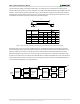
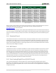
Pmod JA
(XADC)
Pmod JB
(Hi-Speed)
Pmod JC
(Hi-Speed)
Pmod JD
(Hi-Speed)
Pmod JE
(Std.)
Pmod JF
(MIO)
JA1: N15
JB1: T20
JC1: V15
JD1: T14
JE1: V12
JF1: MIO-13
JA2: L14
JB2: U20
JC2: W15
JD2: T15
JE2: W16
JF2: MIO-10
JA3: K16
JB3: V20
JC3: T11
JD3: P14
JE3: J15
JF3: MIO-11
JA4: K14
JB4: W20
JC4: T10
JD4: R14
JE4: H15
JF4: MIO-12
JA7: N16
JB7: Y18
JC7: W14
JD7: U14
JE7: V13
JF7: MIO-0
JA8: L15
JB8: Y19
JC8: Y14
JD8: U15
JE8: U17
JF8: MIO-9
JA9: J16
JB9: W18
JC9: T12
JD9: V17
JE9: T17
JF9: MIO-14
JA10: J14
JB10: W19
JC10: U12
JD10: V18
JE10: Y17
JF10: MIO-15
Table 9. Pmod pinout.
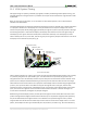
Digilent produces a large collection of Pmod accessory boards that can attach to the Pmod expansion connectors
to add ready-made functions like A/D’s, D/A’s, motor drivers, sensors, and other functions. See
www.digilentinc.com for more information.
The ZYBO has six Pmod connectors, some of which behave differently than others. Each Pmod connector falls into
one of four categories: standard, MIO connected, XADC, or high-speed Table 9 specifies which category each Pmod
falls into, and also lists the Zynq pins they are connected to. The following sections describe the different types of
Pmods.
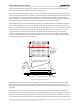
16.1 Standard Pmod
The standard Pmod connector is connected to the PL of the Zynq via 200 Ohm series resistors. The series resistors
prevent short circuits that can occur if the user accidently drives a signal that is supposed to be used as an input.
The downside to this added protection is that these resistors can limit the maximum switching speed of the data
signals. If the Pmod being used does not require high-speed access, then the standard Pmod connector should be
used to help prevent damage to the devices.
16.2 MIO Pmod
The MIO Pmod connector is connected to the MIO bus in the PS of the Zynq via 200 Ohm series resistors. Like the
standard Pmod connector, these series resistors add protection at the cost of maximum switching speed. Since
these data signals are connected to the MIO interface, they can only be accessed by the PS peripheral controller
cores. The GPIO, UART, I2C, and SPI cores can all be used to drive devices connected to this Pmod. Note that the
pin layout of the UART and I2C cores will not align perfectly with the typical Pmod pinouts for these interfaces. This
means that UART or I2C devices connected to this Pmod may require some of the pins to be swapped around
externally using individual wires between the ZYBO and the Pmod.
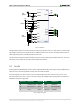
16.3 Dual Analog/Digital Pmod (XADC Pmod)
The on-board Pmod expansion connector labeled “JA” is wired to the auxiliary analog input pins of the PL.
Depending on the configuration, this connector can be used to input differential analog signals to the analog-to-
digital converter inside the Zynq (XADC). Any or all pairs in the connector can be configured either as analog input
or digital input-output.