
Datasheet

PmodDHB1™ Reference Manual
Copyright Digilent, Inc. All rights reserved.
Other product and company names mentioned may be trademarks of their respective owners.
Page 2 of 3
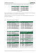
A truth table listing out the various possible combinations and results of the EN and DIR pins is provided below:
DIR1
EN1
Result
DIR2
EN2
Result
0
0
Stop
0
0
Stop
0
1/PWM
Forward
0
1/PWM
Forward
1
0
Stop
1
0
Stop
1
1/PWM
Reverse
1
1/PWM
Reverse
Table 1. Truth table list.
Note that like all H-Bridges, it is recommended that the EN pin is driven to a low voltage state before changing the
voltage state on the DIR pin to ensure that the FETs are not short-circuited.
Two sensor feedback pins for both motors are provided so users can capture the signals coming from any Hall
Effect Sensors in quadrature.
2.1 Pinout Description Tables
Header J1
Pin
Signal
Description
Pin
Signal
Description
1
EN1
Motor 1 Enable
7
EN2
Motor 2 Enable
2
DIR1
Motor 1 Direction
8
DIR2
Motor 2 Direction
3
S1A
Motor 1 Sensor A Feedback
9
S2A
Motor 2 Sensor A Feedback
4
S1B
Motor 1 Sensor B Feedback
10
S2B
Motor 2 Sensor B Feedback
5
GND
Power Supply Ground
11
GND
Power Supply Ground
6
VCC
Power Supply (3.3V/5V)
12
VCC
Power Supply (3.3V/5V)
Header J4 - Motor Voltage
Header J2- M1 JST 6-Pin Motor Connector
Pin
Signal
Description
Header J3- M2 JST 6-Pin Motor Connector
1
VM
Motor Power
Header J8- M2 Feedback
2
GND
Power Supply Ground
Pin
Signal
Description
Header J5 - M1 Power
1
SA2-IN
Sensor A From Motor 2
Pin
Signal
Description
2
SB2-IN
Sensor B From Motor 2
1
M1+
Motor 1 Positive Supply
3
GND
Power Supply Ground
2
M1-
Motor 1 Negative Supply
4
VCC
Power Supply (3.3V)
Header J6- M2 Power
Header J9- Fault
Pin
Signal
Description
Pin
Signal
Description
1
M2+
Motor 2 Positive Supply
1
NFAULT
Overcurrent Condition
2
M2-
Motor 2 Negative Supply
2
GND
Power Supply Ground
Header J7- M1 Feedback
Header J10- Sleep
Pin
Signal
Description
Pin
Signal
Description
1
SA1-IN
Sensor A From Motor 1
1
NSLEEP
Puts device into sleep state
2
SB1-IN
Sensor B From Motor 1
2
GND
Power Supply Ground
3
GND
Power Supply Ground
4
VCC
Power Supply (3.3V)