
Datasheet

1300 Henley Court
Pullman, WA 99163
509.334.6306
www.digilentinc.com
PmodDHB1™ Reference Manual
Revised May 24, 2016
This manual applies to the PmodDHB1 rev. B
DOC#: 502-259
Copyright Digilent, Inc. All rights reserved.
Other product and company names mentioned may be trademarks of their respective owners.
Page 1 of 3
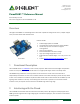
Overview
The Digilent PmodDHB1 is a dual H-Bridge motor driver that is capable of driving two DC motors, a bipolar stepper
motor, and other devices with inductive loads.
1 Functional Description
The PmodDHB1 utilizes TI's DRV8833 to drive a variety of systems. With the two built in H-Bridges and pull down
resistors on the inputs, users may run two DC motors or a single bipolar stepper motor in fast decay mode.
The DRV8833 chip provides over-current protection on the motor drive circuits. Each internal drive FET is
independently monitored for an over-current condition and will be shut down internally to protect the chip. When
an over-current condition is sensed the chip will shut down the FET with the fault and then set the NFAULT pin low
signaling a fault condition on the chip. The remaining FETs will continue to operate as normal. When the fault
condition is over, the chip will self-reset and return the NFAULT logic level to logic high.
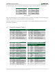
2 Interfacing with the Pmod
The PmodDHB1 communicates with the host board via the GPIO protocol. By driving the enable (EN) pins with a
PWM signal and a logic level low or high voltage signal on the direction (DIR) pins, users are able to run DC motors
at various speeds.
The PmodDHB1.
Dual H-Bridge capable of 1.5A RMS
Two quadrature encoder channels for motor feedback
Two JST 6-pin ports for connection to Digilent
motor/gearbox
Over-current protection
Recommended 10.8 V max motor voltage
Logic input voltage range of 2.5 V to 5 V
Small PCB size for flexible designs 1.3“ × 1.8” (3.3 cm × 4.6
cm)
Follows Digilent Pmod Interface Specification Type 5
Features include: