
Information


PmodIA™ Reference Manual
Copyright Digilent, Inc. All rights reserved.
Other product and company names mentioned may be trademarks of their respective owners.
Page 4 of 5
2) Enter the initialize mode by sending an initialize with start frequency command to the control register.
This allows the circuit being measured to reach its steady state.
3) Start the frequency sweep by sending the start frequency sweep command to the control register.
1.4 Impedance Calculations
The analog-to-digital converter samples the frequency response from unknown impedances at up to 1MSPS with
12-bit resolution for every point in the frequency sweep. Before storing the measurements, the PmodIA performs
a Discrete Fourier Transform (DFT) on the sampled data (1,024 samples for each frequency step). Two registers
store the DFT result: the Real Register, and the Imaginary Register.
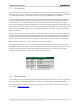
Electrical impedance contains both real and imaginary numbers. In Cartesian form, you can express impedance
with the equation:
Where Real is the real component, Imaginary is the imaginary component, and is an imaginary number
(equivalent to
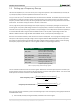
, in mathematics). You can also represent impedance in polar form:
Where
is the magnitude and θ is the phase angle:
The PmodIA does not perform any calculations. After each DFT, the master device must read the values in the Real
and Imaginary registers.
In order to calculate the true impedance, you must take into account the gain. You can find an example gain factor
calculation in the AD9533 data sheet.
1.5 Temperature Readings
The PmodIA has a self-contained, 13-bit temperature sensor to monitor device temperature. Please refer to the
AD5933 data sheet for more information on controlling this module.
1.6 Register Addresses
The AD5933 data sheet has a complete table of register addresses.
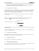
2 Physical Dimensions
The pins on the pin header are spaced 100 mil apart. The PCB is 1.6 inches long on the sides parallel to the pins on
the pin header and 0.8 inches long on the sides perpendicular to the pin header.