
Manual


Cerebot 32MX4 Reference Manual
www.digilentinc.com page 8 of 15
Copyright Digilent, Inc. All rights reserved. Other product and company names mentioned may be trademarks of their respective owners.
Connector and Jumper Block Pinout Tables
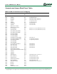
MCU Port Bit to Pmod Connector Pin Mapping
MCU Port
Bit
Signal Connector
Pin
Notes
RA00 TMS/RA0 N/A Used by debug circuit
RA01 TCK/RA1 N/A Used by debug circuit
RA02 SCL2/RA2 JF-01 Shared with I2C daisy chain #2, J6
RA03 SDA2/RA3 JF-02 Shared with I2C daisy chain #2, J6
RA04 TDI/RA4 N/A Used by debug circuit
RA05 TDO/RA5 N/A Used by debug circuit
RA06 TRCLK/RA6 JF-03 Shared with BTN1
RA07 TRD3/RA7 JF-04 Shared with BTN2
RA09 PMA7/Vref-/CVref-/RA9 JK-07
RA10 PMA6/Vref+/CVref+/RA10 JK-08
RA14 SCL1/INT3/RA14 N/A I2C Bus #1, J2, not shared with Pmod connector
RA15 SDA1/INT4/RA15 N/A I2C Bus #1, J2, not shared with Pmod connector
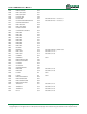
RB00 PGD1/EMUD1/AN0/CN2/RB0 JJ-01
RB01 PGC1/EMUC1/AN1/CN3/RB1 JJ-02
RB02 C2IN-/AN2/CN4/RB2 JJ-03
RB03 C2IN+/AN3/CN5/RB3 JJ-04
RB04 C1IN-/AN4/CN6/RB4 JJ-07
RB05 VBUSON/C1IN+/AN5/CN7/RB5 JJ-08 Selected by J16
RB06 PGC2/EMUC2/AN6/OCFA/RB6 N/A Used by debug circuit, PGC
RB07 PGD2/EMUD2/AN7/RB7 N/A Used by debug circuit, PGD
RB08 C1OUT/AN8/RB8 JJ-09
RB09 C2OUT/AN9/RB9 JJ-10
RB10 CVrefout/PMA13/AN10/RB10 JK-01 Shared with LD1
RB11 PMA12/AN11/RB11 JK-02 Shared with LD2
RB12 PMA11/AN12/RB12 JK-03 Shared with LD3
RB13 PMA10/AN13/RB13 JK-04 Shared with LD4
RB14 PMALH/PMA1/AN14/RB14 JB-10
RB15 PMALL/PMA0/AN15/OCFB/CN12/RB15
JB-07
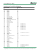
RC01 T2CK/RC1 JD-04
RC02 T3CK/RC2 JD-10
RC03 T4CK/RC3 JE-10
RC04 SDI1/T5CK/RC4 JK-10 Shared with SPI Port 1 Connector, J1
RC12 OSC1/CLKI/RC12 N/A Primary Oscillator Crystal
RC13 SOSCI/CN1/RC13 N/A Secondary Oscillator Crystal
RC14 SOSCO/T1CK/CN0/RC14 N/A Secondary Oscillator Crystal
RC15 OSC2/CLKO/RC15 N/A Primary Oscillator Crystal
RD00 SDO1/OC1/INT0/RD0 JH-08 Shared with SPI Port 1 Connector, J1
RD01 OC2/RD1 JD-02
RD02 OC3/RD2 JD-08
RD03 OC4/RD3 JE-08
RD04 PMWR/OC5/CN13/RD4 JB-09