
Datasheet


CoolRunner-II™ Starter Board Reference Manual
Copyright Digilent, Inc. All rights reserved.
Other product and company names mentioned may be trademarks of their respective owners.
Page 2 of 4
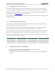
JA
Pmod
Connectors
8
32
Expansion
Hole Pattern
Discera
Oscillator
SPI ROM
JTAG
Atmel USB
Controller
XC2C256
TQ144
External
Power
Connector
Maxim
Regulators
USB
14
JTAG
Header
V
io1
(3.3V)
V
io1
(3.3V)
V
core
(1.8V)
JP2
User I/O:
Seven-Segment
LED Display,
Pushbuttons,
Slide Switches,
and LEDs
2
2
4
12
JB
JC
JD
4
8
8
8
Parallel
User I/O
JP3
En
1 Configuration
The CoolRunner-II board's CPLD must be configured (or programmed) by the user before it can perform any
functions. Files can be created from schematics or HDL source files using the free ISE WebPack software from
Xilinx. Configuration files can be transferred to the CoolRunner-II board using a USB cable and Xilinx's iMPACT
software or using an external programming cable (not included). Once configured, the CPLD retains its state
indefinitely. When the CoolRunner-II board is powered on, the most recently loaded CPLD configuration is
available immediately. A new configuration can be loaded at any time, and as soon as a new configuration is
loaded, it defines the CPLD's behavior.
2 Power Supplies
The CoolRunner-II board can be powered from its integral USB port or from an external supply attached at
connector JP3. Jumper JP2 selects whether the board uses USB power or external power. External power, from any
source, is routed through a Maxim LT3028 regulator to produce the two voltage supplies (3.3V I/O and 1.8V core)
required by the CPLD. Whenever board power is applied, the power-on LED glows.
To use an external power source, set jumper JP2 to BAT and apply power to the JP3 pins (see the board's silkscreen
for orientation). Any 4.5V to 9V power supply can be used (for example, a transistor battery or a series
arrangement of AA cells).
The CoolRunner-II board uses a four-layer PCB, with the inner layers dedicated to V
CC
and GND. The Maxim
regulators, together with good power supply routing and ample bypass capacitors on all IC pins, results in a low-
noise power supply.