
Owner manual


Genesys Reference Manual
www.digilentinc.com page 27 of 28
Copyright Digilent, Inc. All rights reserved. Other product and company names mentioned may be trademarks of their respective owners
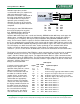
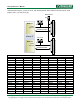
Pmods use 2x6 right-angle, 100-mil connectors that mate with standard 2x6 pin headers available
from a variety of catalog distributors. Each 12-pin Pmod connector provides two VCC signals (pins 6
and 12), two Ground signals (pins 5 and 11), and eight logic signals. VCC and Ground pins can
deliver up to 1A of current, and a jumper block is available for each connector to choose the VCC
voltage: regulated 3.3V or the unregulated board input voltage (VU). Pmod data signals are not
matched pairs, and they are routed using best-available tracks without impedance control or delay
matching.
Digilent produces a large collection of accessory boards that can attach to the Pmod and VHDC
expansion connectors to add ready-made functions like A/D’s, D/A’s, motor drivers, sensors, cameras
and other functions. See www.digilentinc.com for more information.
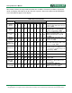
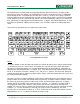
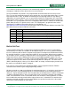
Pmod Connector Pinouts
Pmod A Pmod B Pmod C Pmod D
Signal Pin Signal Pin Signal Pin Signal Pin
JA1 AD11 JB1 AE9 JC1 AL11 JD1 AN14
JA2 AD9 JB2 AC8 JC2 AJ10 JD2 AN13
JA3 AM13 JB3 AB10 JC3 AK9 JD3 AP12
JA4 AM12 JB4 AC9 JC4 AF9 JD4 AL10
JA7 AD10 JB7 AF8 JC7 AK11 JD7 AP14
JA8 AE8 JB8 AB8 JC8 AC10 JD8 AN12
JA9 AF10 JB9 AA10 JC9 AJ9 JD9 AM11
JA10 AJ11 JB10 AA9 JC10 AA8 JD10 AK8
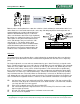
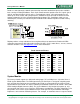
System Monitor
The Genesys board supports the dedicated analog inputs (VP and VN pins on J13) to the Virtex 5
FPGA System Monitor block. The PCB layout for the VP and VN pins is designed using differential
pairs and anti-alias filtering in close proximity to the FPGA as recommended in the Virtex 5 FPGA
System Monitor User Guide. The Virtex 5 FPGA System Monitor function is built around a 10-bit, 200-
kSPS Analog-to-Digital Converter (ADC). The System Monitor is fully functional on power up, and
measurement data can be accessed via the JTAG port pre-configuration. The Xilinx ChipScope™ Pro
tool provides access to the System Monitor over the JTAG port. The System Monitor control logic
implements some common monitoring features. For example, an automatic channel sequencer allows